Final Motor Specs
As described in the last post, the motor build is mostly completed. There are a few weird odds-and-ends yet to be done, like a drill and tap for a bolt to secure warm-up regulator to the block and such – nothing major. But I realized that the final build specifications were never discussed fully. So here’s a chart and explanation of my build, comparing it to stock BMW and the Alpina build.
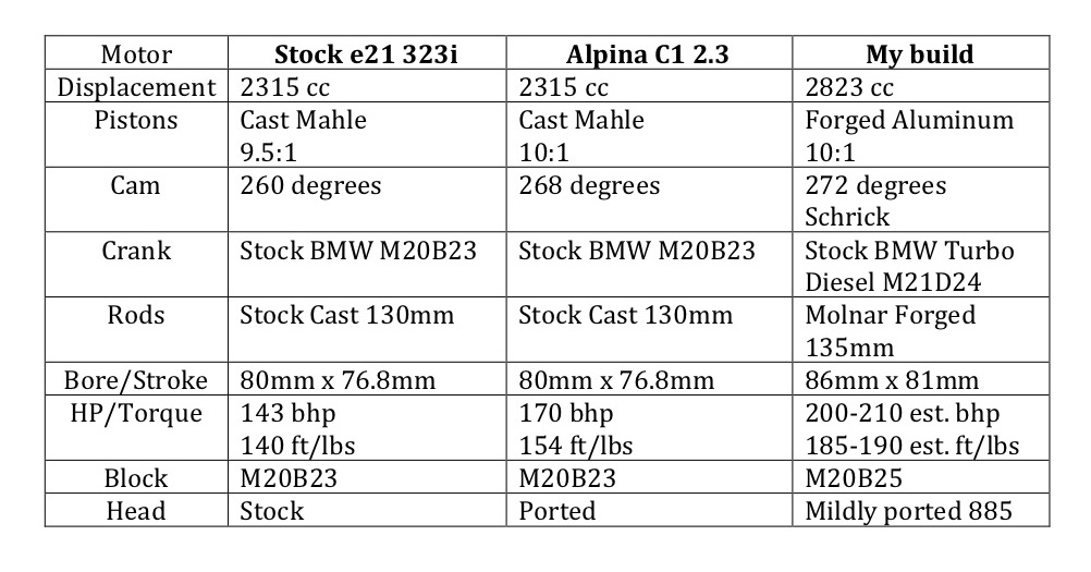 Virtually every decision-point was vetted. Twenty-eight hundred cc displacement was chosen because I wanted to use a turbo-diesel crank (it’s a very stout crack, able to withstand the high pressures of the diesel motor) and I always kinda liked the e30 c2 2.7, based on the same crank and big bore. The pistons were an easy decision, given the crank and desire to get at least 2700cc. I didn’t feel the need for a much bigger bore and knew that several folks had successfully used a 86 mm bore on the stock 325i M20 block.
The rods were a compromise. Because the pistons were custom, I could use virtually any BMW rod that fit the crank. If I used stock BMW rods, I would spend money buying them, testing and refreshing them, and lightening and balancing them. If I went with proven, USA forged rods like Carrillo or such I’d spend a fortune. For the same price as used rods plus machine shop work, however, I could get forged Chinese rods that were finished in the USA by a reputable shop. That is just what I did, with 135mm rods from Molnar Technologies. Tom Molnar was the Metallurgist and engineer for Oliver Rods and Cranks for over 20 years; he was the founder of K-1 Technologies and recently started his own shop. I was confident with that background that my compromise rods were built by someone with the necessary know-how.
The Schrick 272 was also a compromise camshaft, but for different reasons. Retaining the Bosch K-Jet fuel injection was the limiting factor. From what I’ve been told, the flap in the air-fuel meter is sensitive to pressure changes in the intake plenum and a higher-duration cam will create too much pressure change for the K-Jet fuel injection. Normally, with the increased displacement, I would build in more cam – and while the Schrick 272 is a “bigger” cam than the stock Alpina 268, it is not monumentally so. Obviously, it’s only 4 degrees more duration than the Alpina cam and 12 more than BMW. In the faux A4S I built, for example, I had 2.2 liters of displacement (S14 crank in stock M10 block) and a Schrick 304. The 304 has significantly more duration than the 264 degree stock M10 cam and is usually thought to be too much cam for the street, with high horsepower but little bottom-end power. But the increased displacement made up for that and the motor was actually very docile and flexible – lots of horsepower but the increased cubic inches (or centimeters, as the case may be) gave it lots of low-end torque. If I could have done that here, I would have. But no such luck and the 272 was the most duration I could comfortably get while retaining the stock(ish) K-Jet fuel injection.
The M20B25 block was chosen simply for convenience – there are a ton of them available and but for the drill-and-tap for warm-up regulator, there are no practical differences. The 885 head is said to flow best of the available M20 heads, so that choice was simple too. The head and intake plenum were mildly ported and matched.
I guestimate the motor to put out about 200 horsepower and 185 foot-pounds of torque. Both numbers represent a gain of 30 horsepower and foot-pounds. The horsepower is an educated guess, starting at the Alpina 170 mark for the 2.3 liter C1 motor and then comparing to the Alpina B6 2.8, which has a tad less displacement (2788 v. 2823). The B6 motor puts out 200 or 218, depending on fuel injection and cam. The Pierburg version of the B6, with an airflow meter similar to the K-Jet and a 260 degree cam, puts out 200. The Bosch L-Jet version with a 280 degree cam, puts out 218. Mine is probably somewhere in between but 200 should be a safe number, given the displacement, cam, compression ratio and fuel injection. (Note that Alpina used considerably less cam duration for fuel injection similar to mine.)
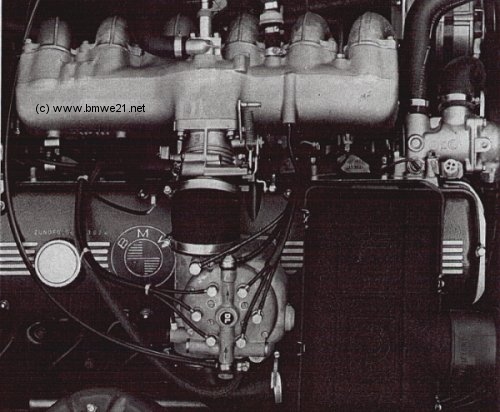 For torque I used the B6 2.8 as a reference point as well. The early B6 motor put out 182 and the later 195. Mine should be in the middle as well but 185 is a safe number.
If these numbers are right, I will be getting B6 performance essentially with weight savings of 57 pounds – all at the nose. (The M20 weight is 258 lbs while the M30 is 315 pounds.) That’s not bad!
A comparison of the C1 and B6 specs can be found here: http://www.bmwe21.net/?page_id=301
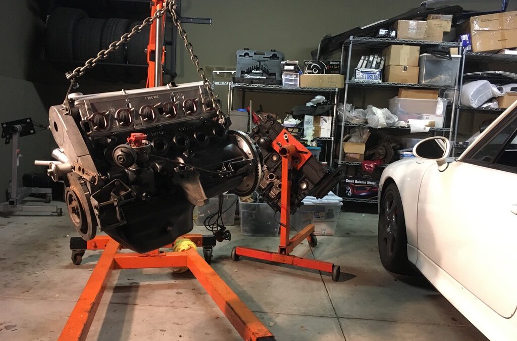
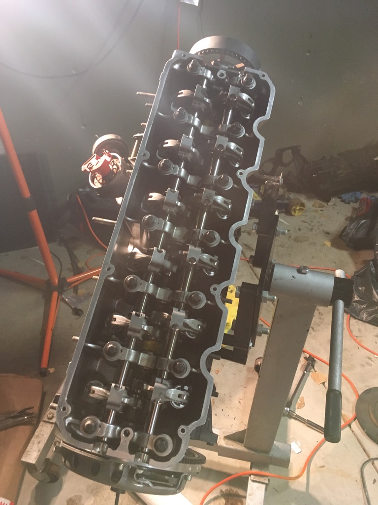 And then the drive belt and the pulleys.
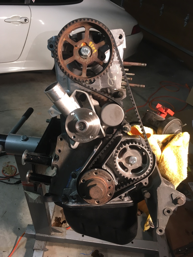 Then the oil pan was ready to go on.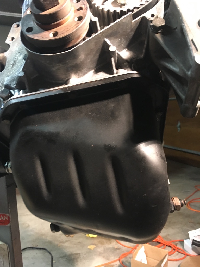
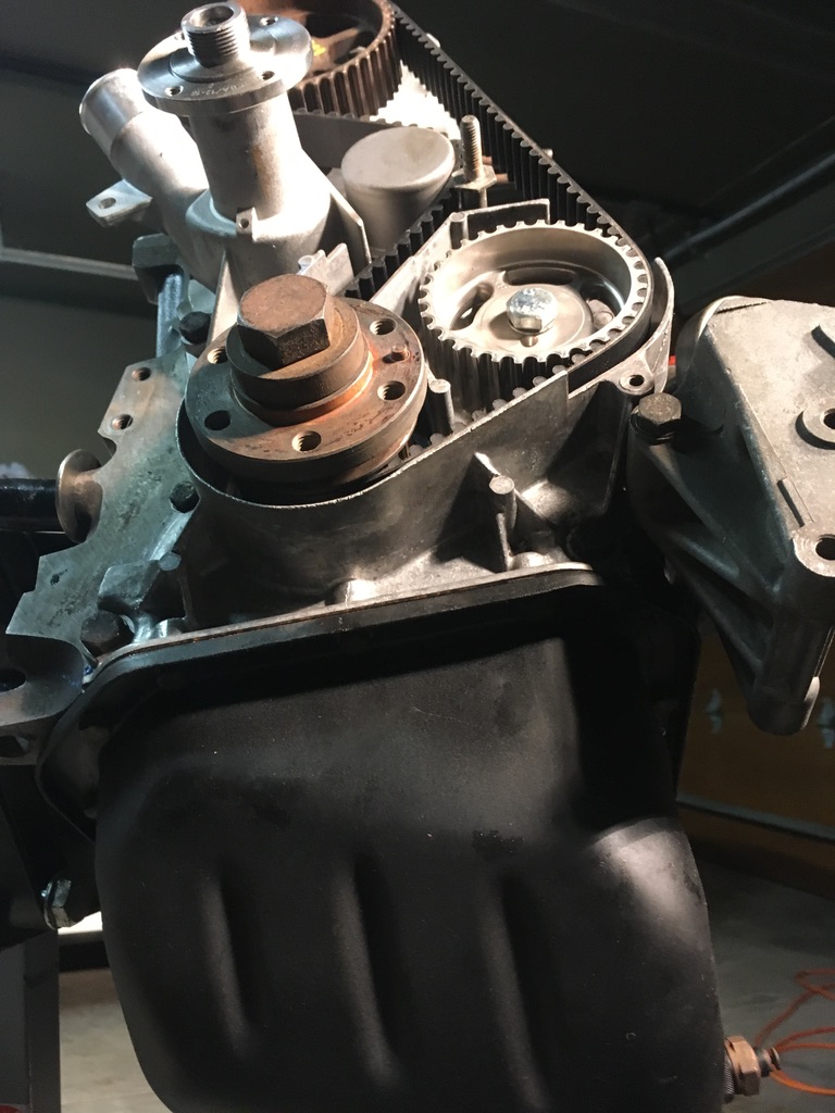 And then the rest of the rotating mass and the front covers.
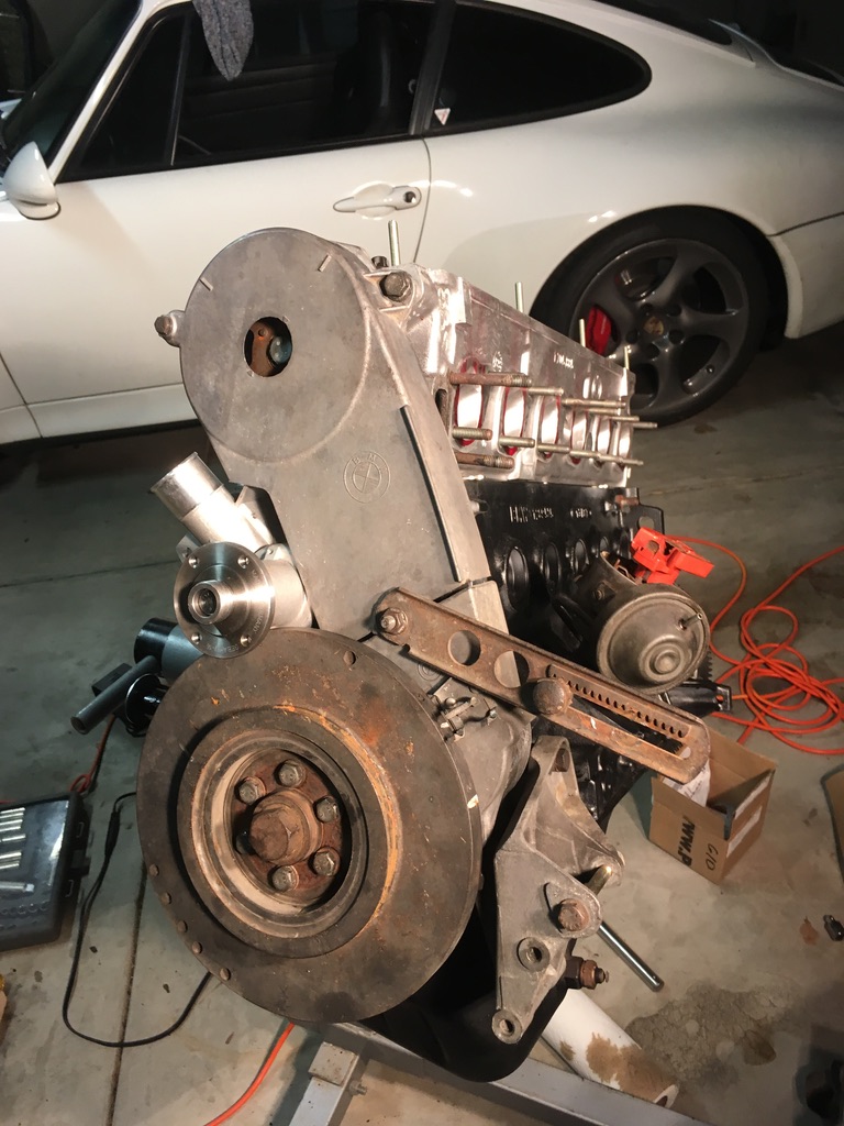 Once the motor was assembled, I was able to take some time to appreciate the machine work. Here, the intake ports were gasket matched to the intake manifold.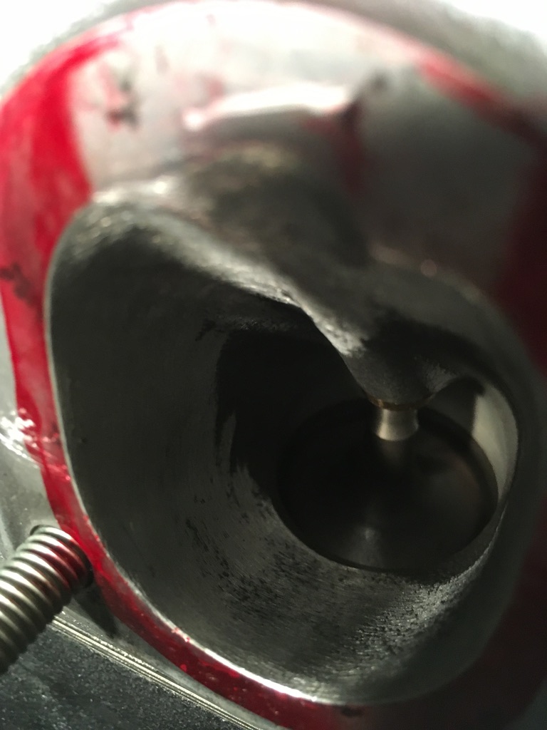
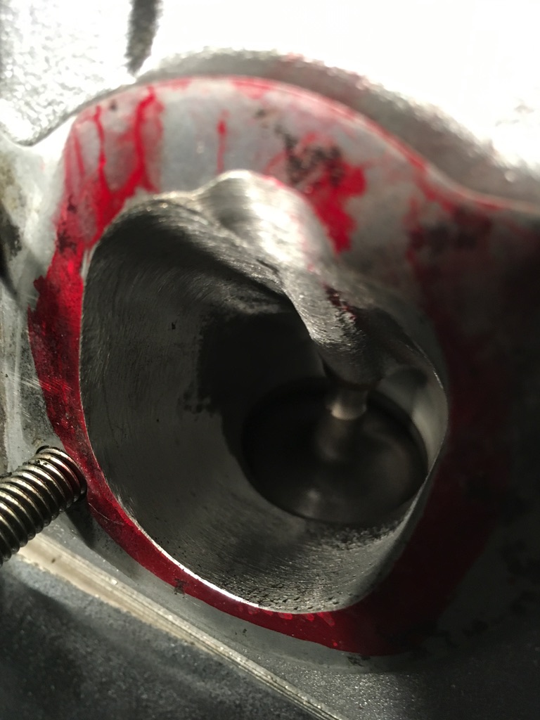
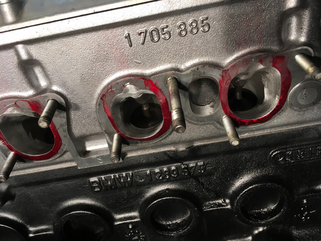
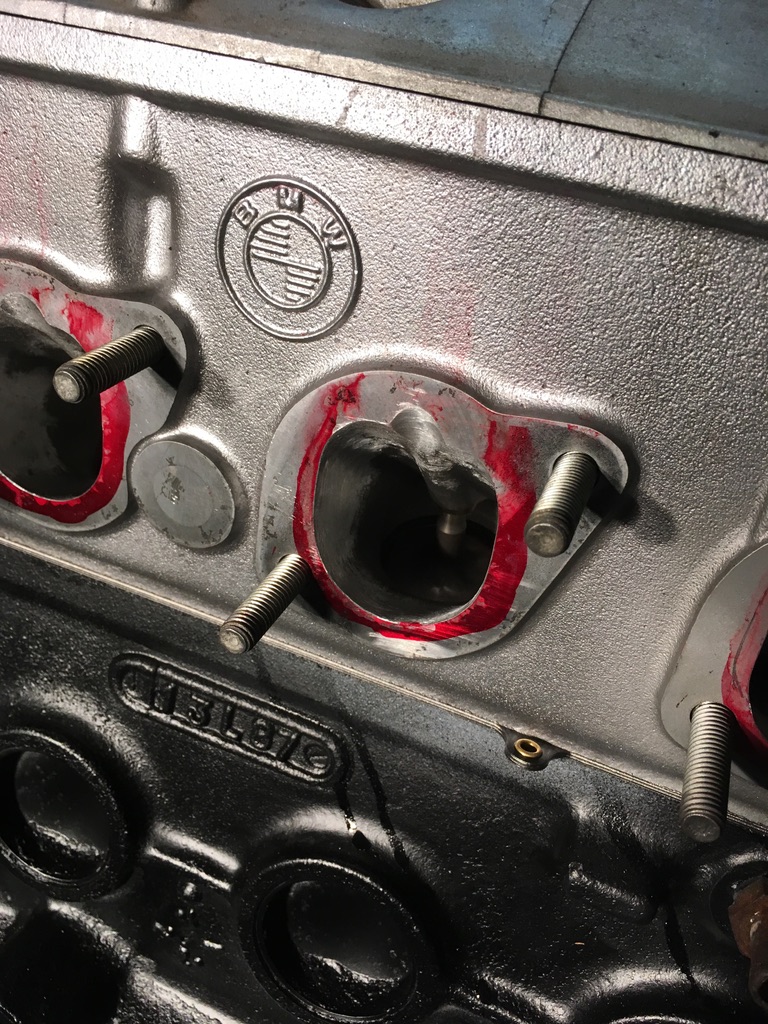 And visa-versa for the intake manifold.
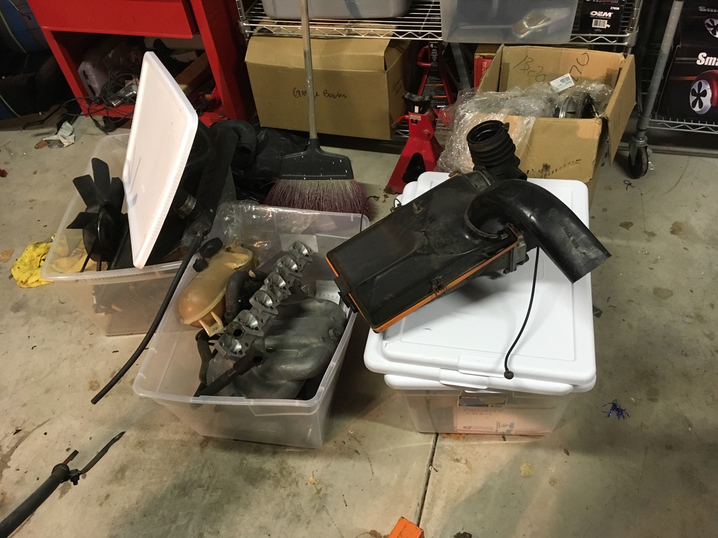
 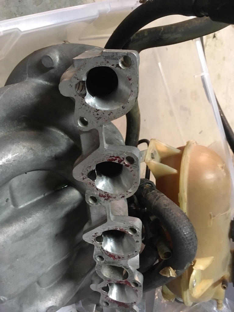 I made plans with Stu for him to bring his X5 down to my house and pick up the motor and the various parts. That meant next up for me was organizing the other parts. Got a couple or four bins of parts together.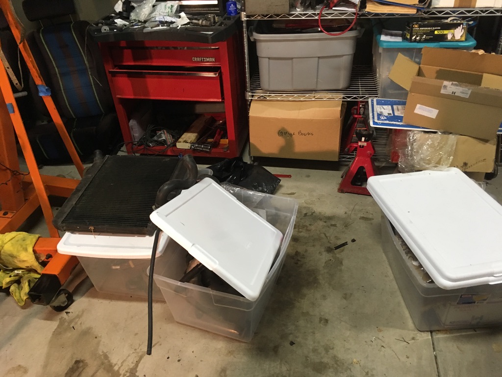
 And put the motor on the cherry picker.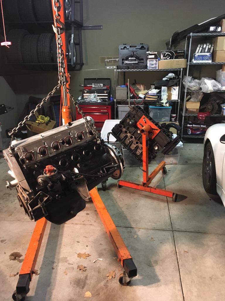
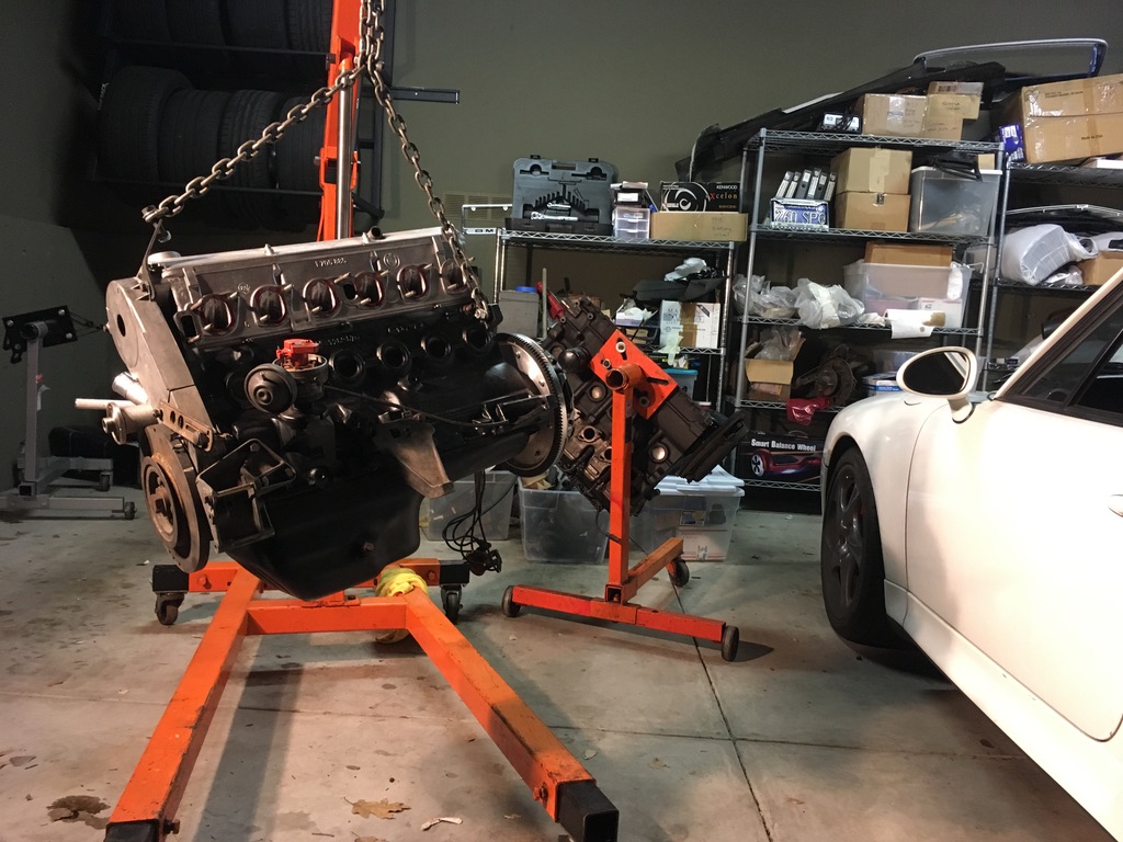
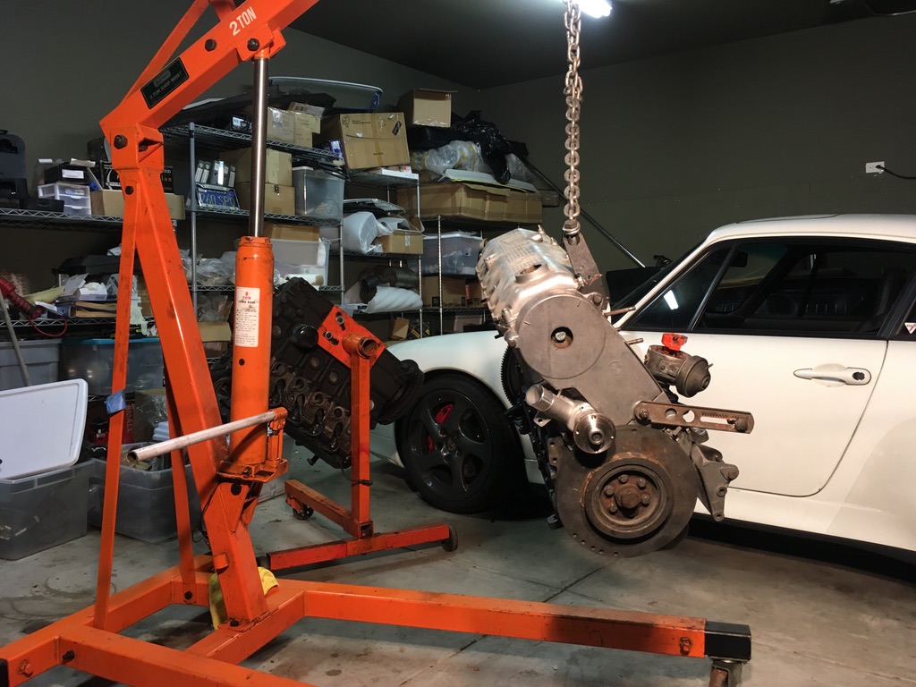 Stu came and picked up the motor late one night, and after getting it to his shop, he had a chance to look it over. After looking at the intake manifold, he asked if it was ok for him to smooth the porting out a little. Of course! He also wants to pretty up the front covers and the harmonic balancer on the front crank pulley. Why not! I’m sure these will delay the project some more, but I clearly am not making my original goal of a late August debut at Monterey, so I have another year to get everything done.
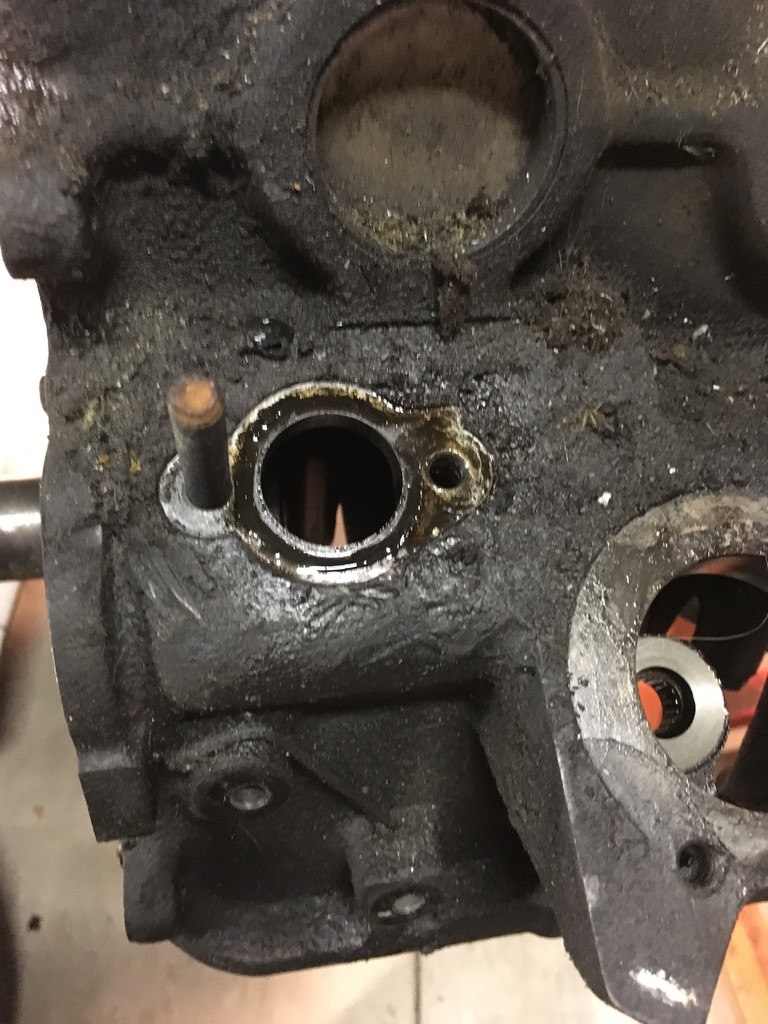
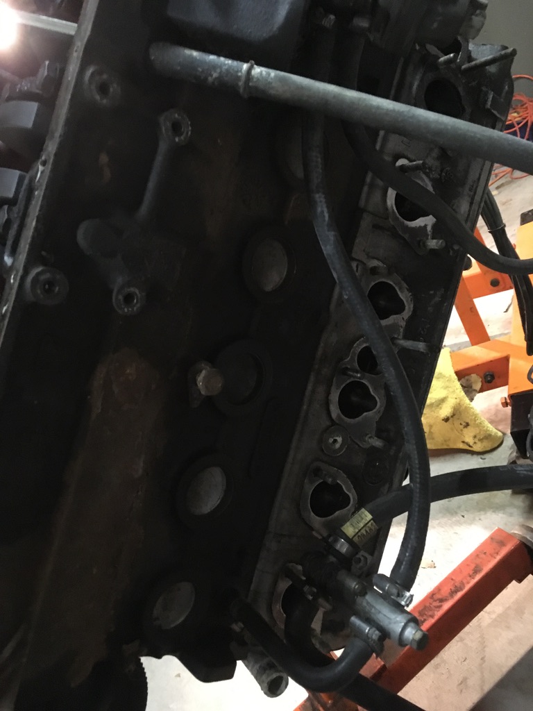 When wrenching on that, something interesting was discovered. The warm-up regulator bolts to the block (on top of a manifold that has coolant running through it). When unbolting those for Stu to take to Sacramento, we found the bottom of the manifold is exposed to the sump, with a bore through the block and a nice rubber gasket to keep it sealed. Why? What does that accomplish? The m10 K-Jet doesn’t do that and we can’t figure out why the M20 does – so, is it necessary to bore out the new block? We don’t think so, but if you know otherwise, feel free to let me know.
 Next up is pulling the Alpina motor apart and figuring out what is in there and whether the head gasket is blown. Then I’ll clean it up and freshen up the innards.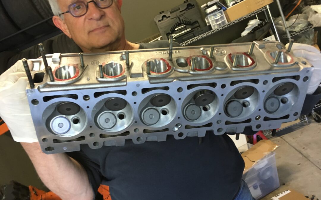
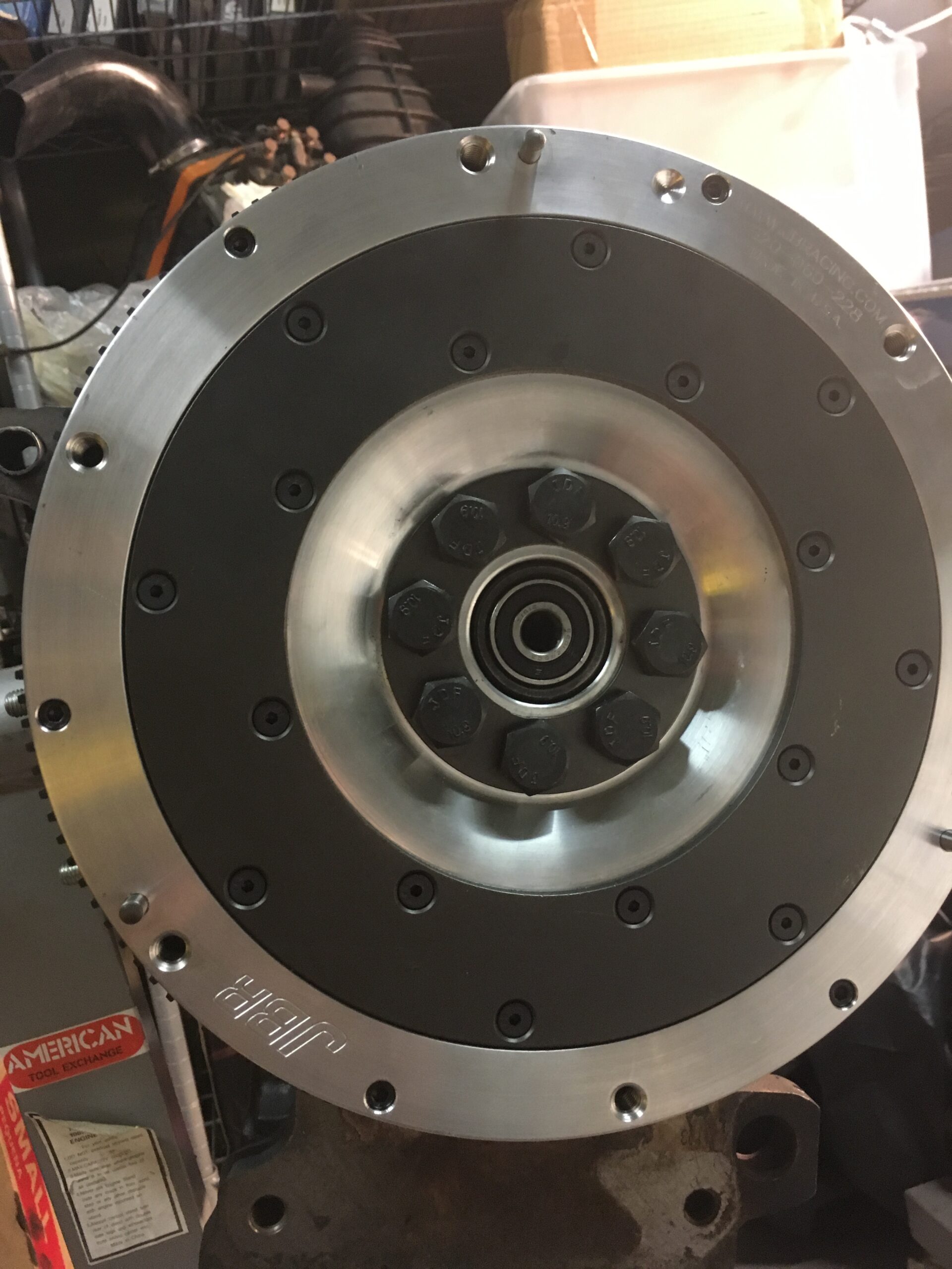
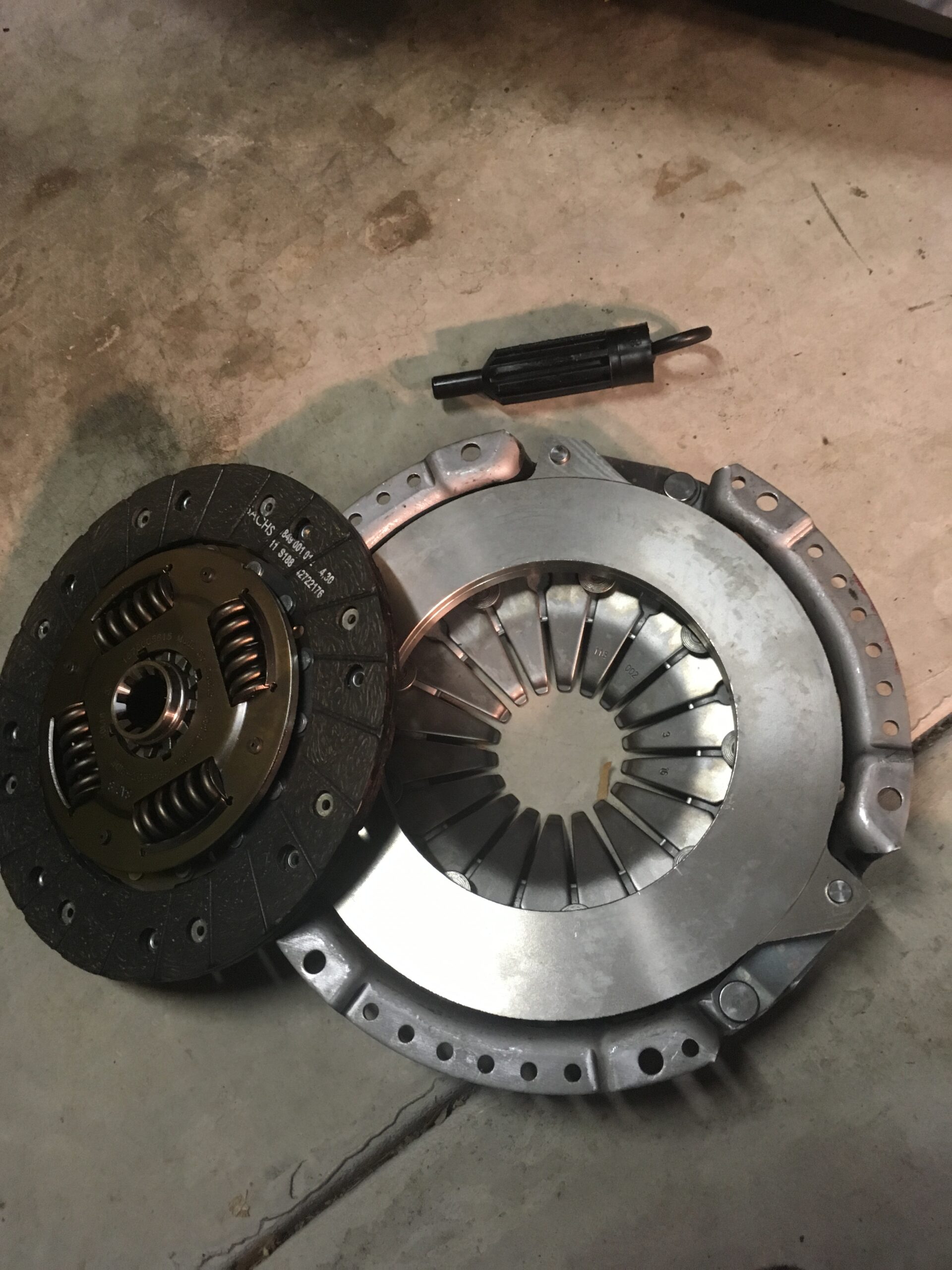
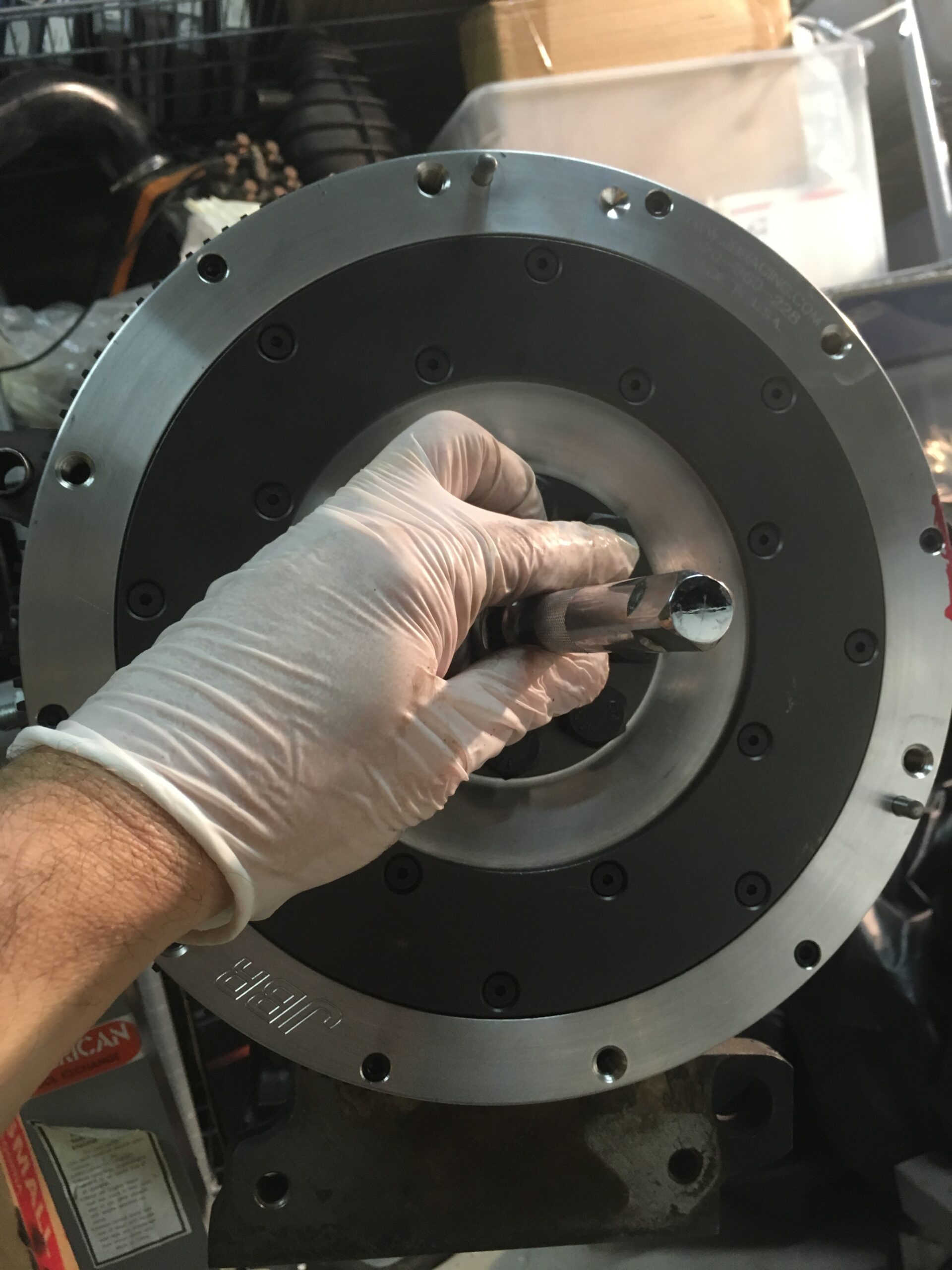
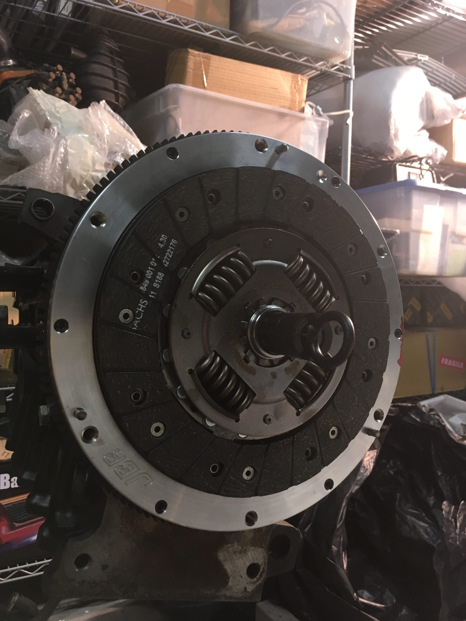
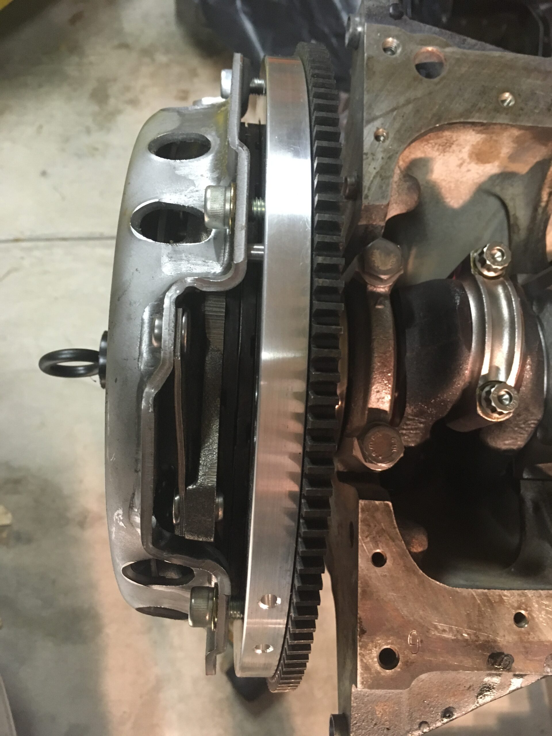
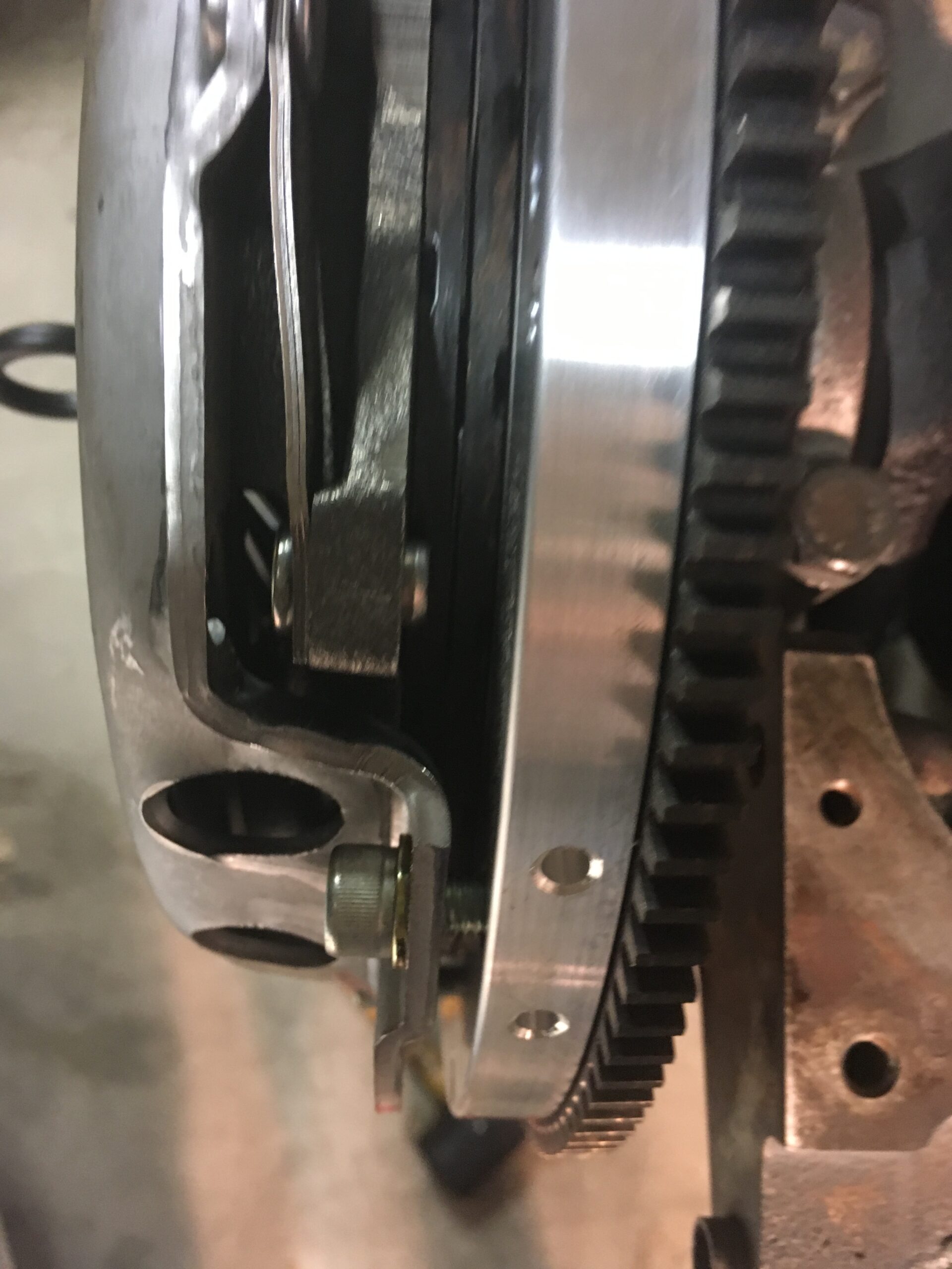
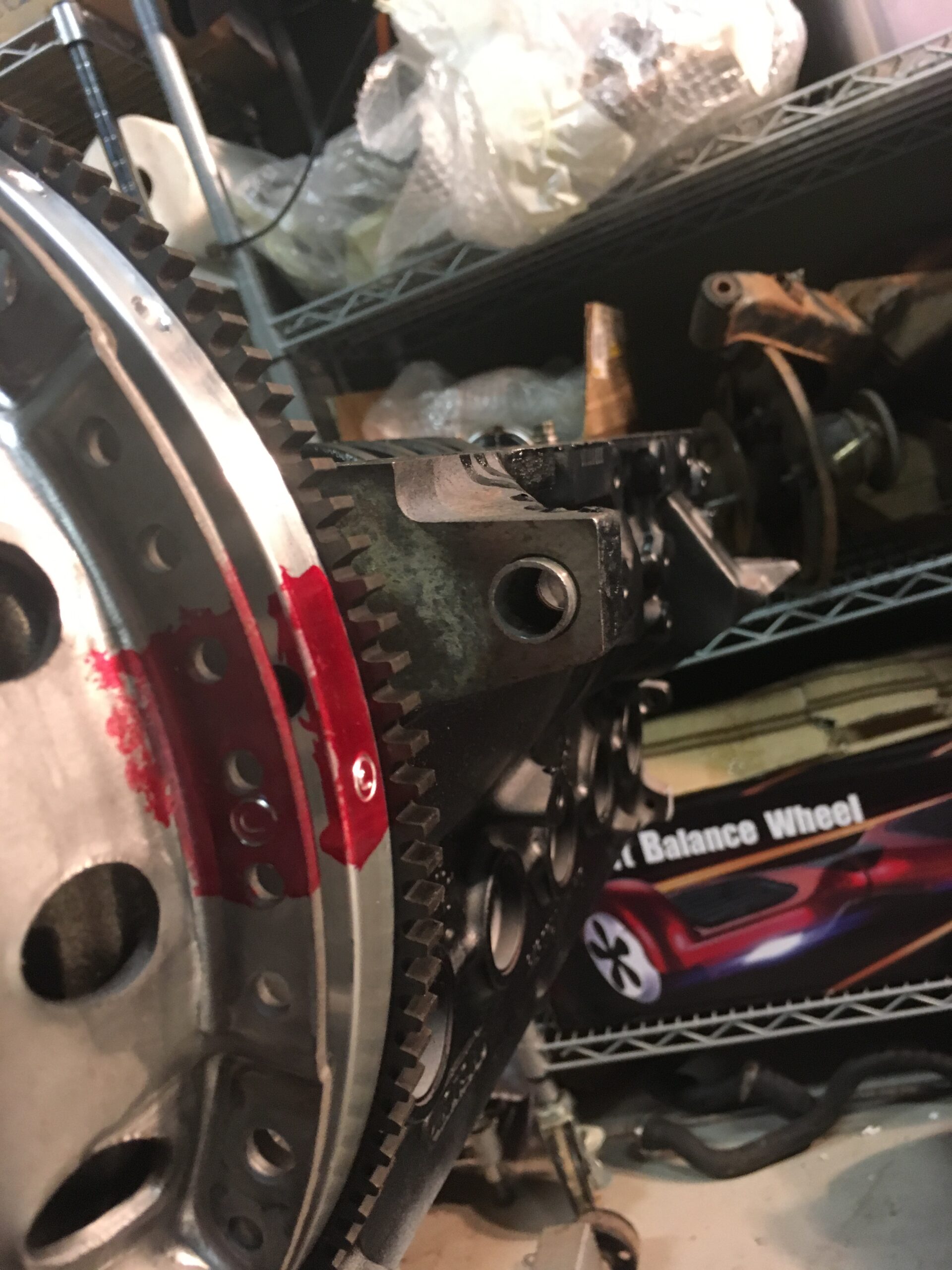
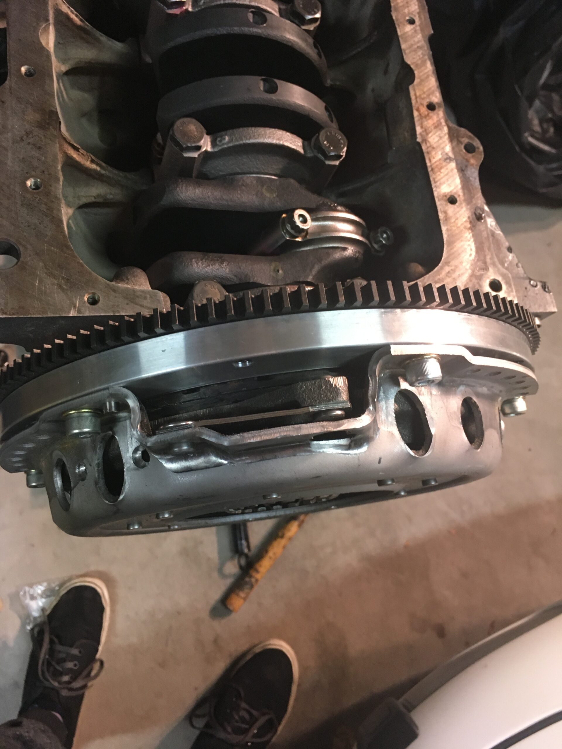
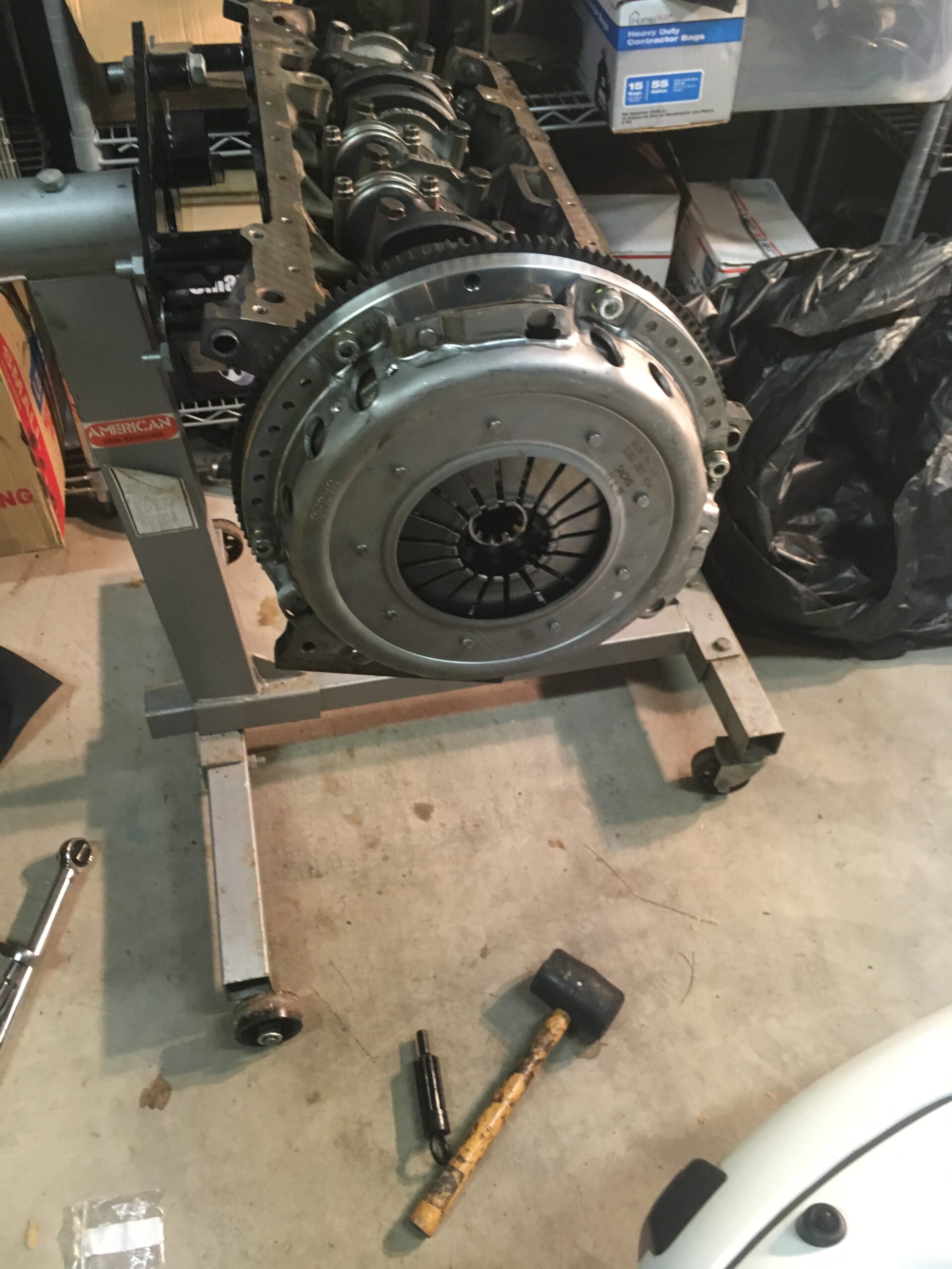 Shortly after doing that, I realized I made a bone-headed mistake and didn’t install the rear main seal nor its housing. A legitimate question: How could this happen? The best excuse I have is that I haven’t disassembled the original engine, bought a used block and that part wasn’t included – and then, in all the excitement of getting the rotating assembly together, I simply forgot about such things.
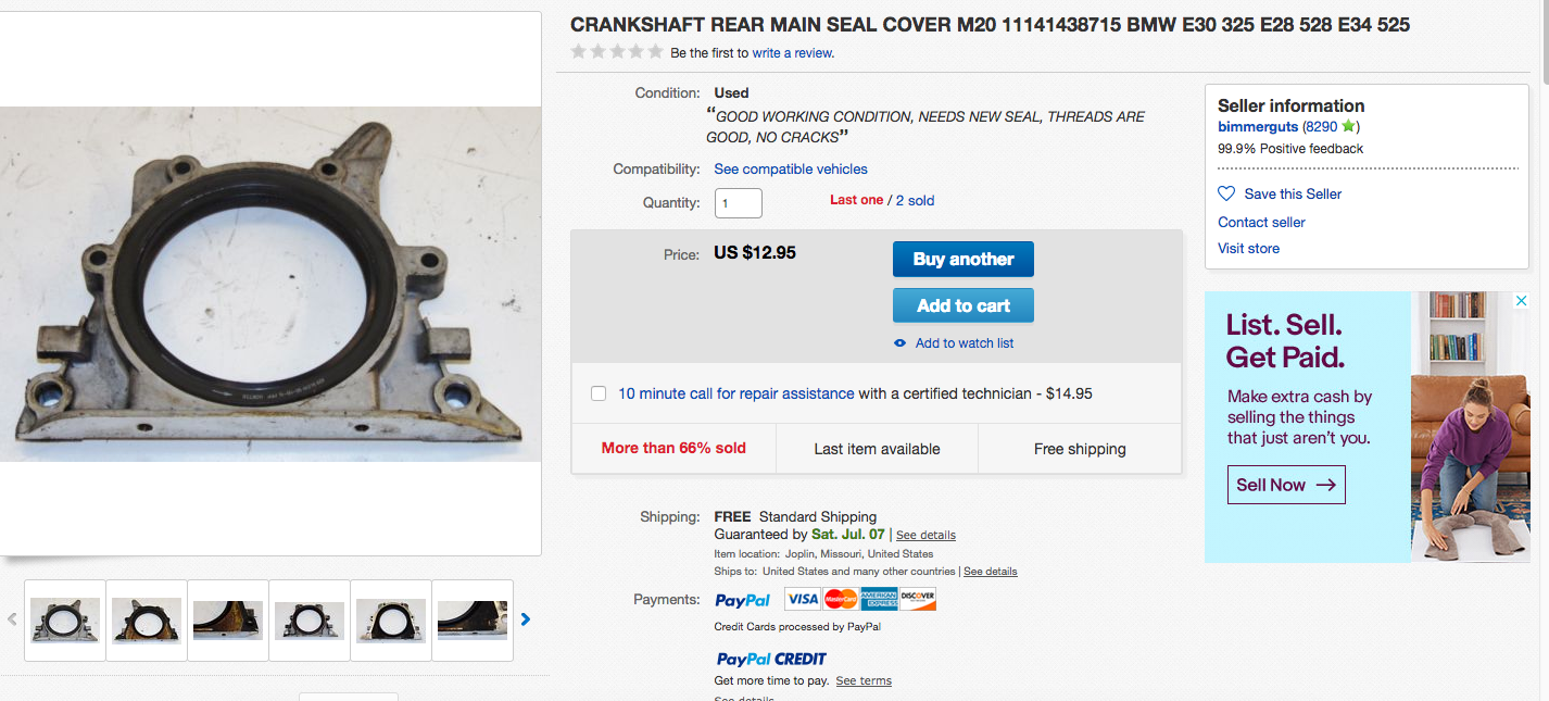 Having never work on an M20 motor before – let alone built one – the next steps vexed me. Unsure of how to tackle it, I started taking the front covers and hubs around the timing belt.
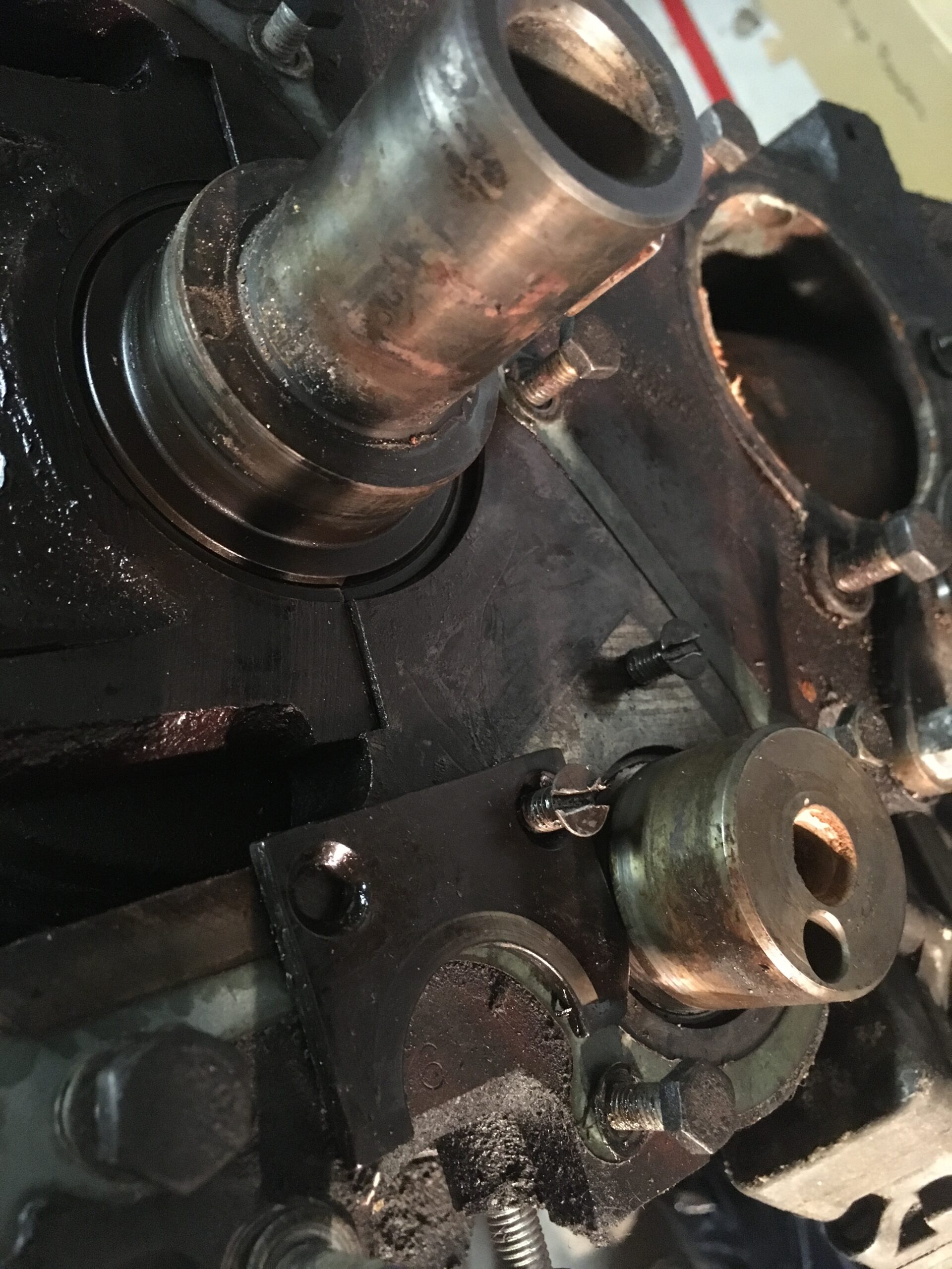
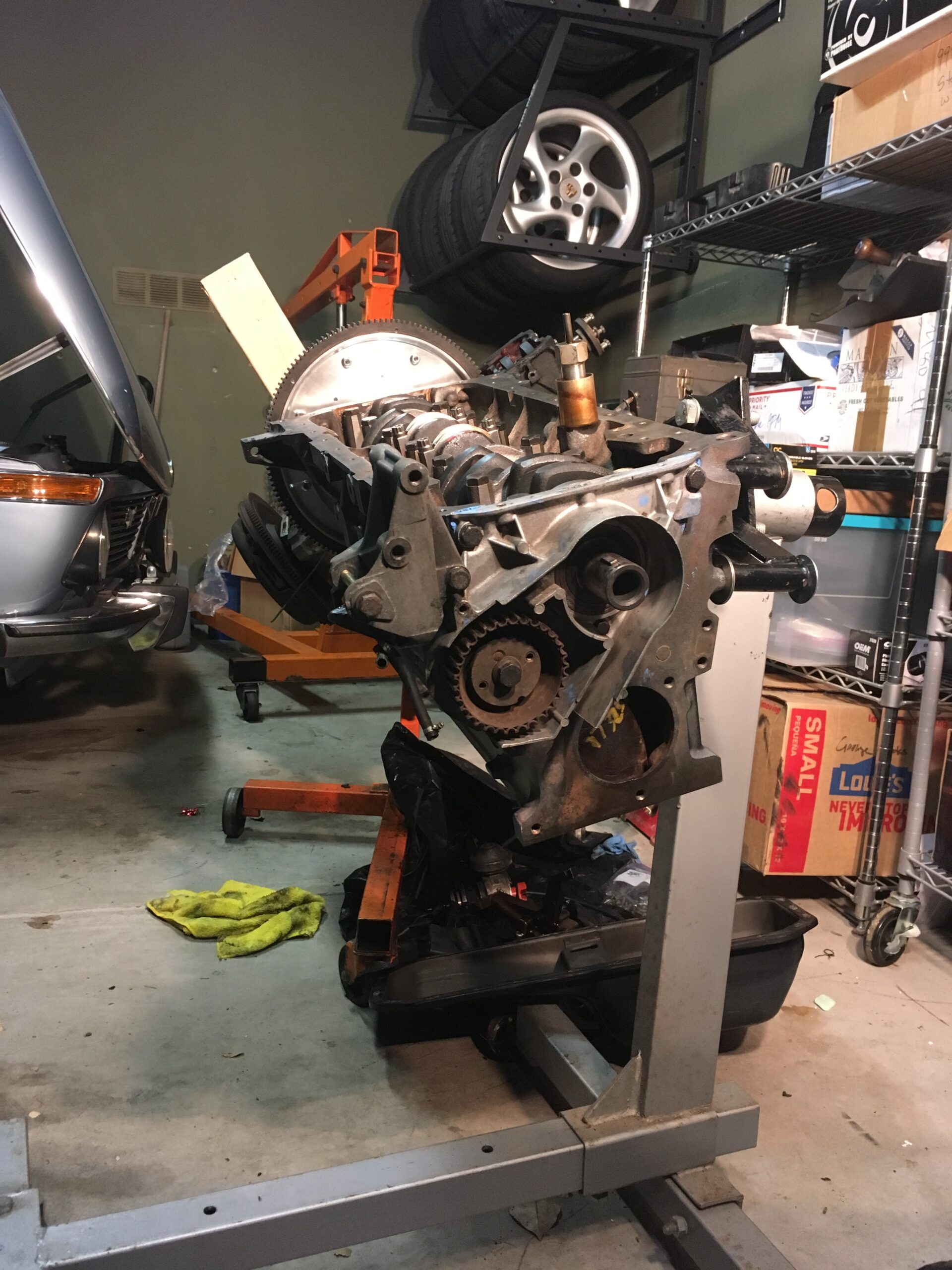 This went smoothly until I encountered the screws securing the intermediate shaft drive. For some reason, instead of using allen screws, BMW used standard head machine screws. Given the torque on these, one simply refused to loosen. Worse, I started to strip the head as I tried. I went into the house, had a beer, and thought about how to get that thing loosened. It came to me: An impact screwdriver!
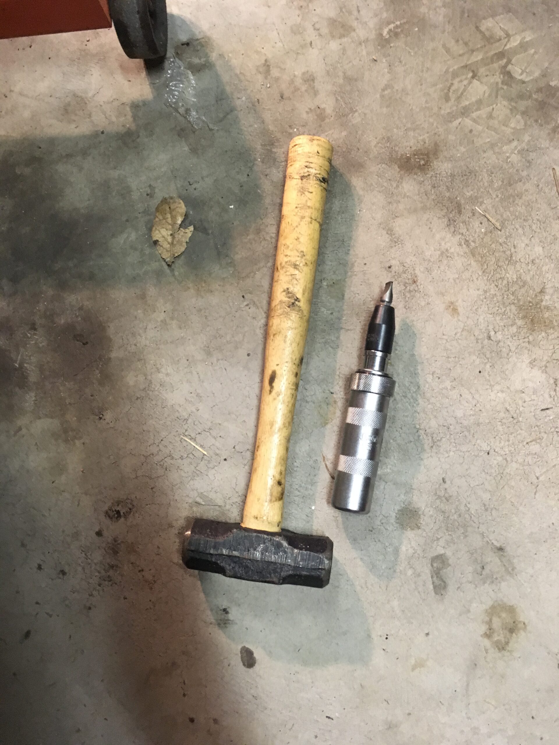 Once that arrived, it was simply a matter of a few blows with the mallet, a few more, a couple more for good measure, and the uncooperative screw was beaten into submission, first barely turning but with each blow going a bit further until I was able to remove it with a normal screwdriver. The intermediate shaft drive was off and the new one on! For good measure, new screws holding the drive were ordered and installed, too.
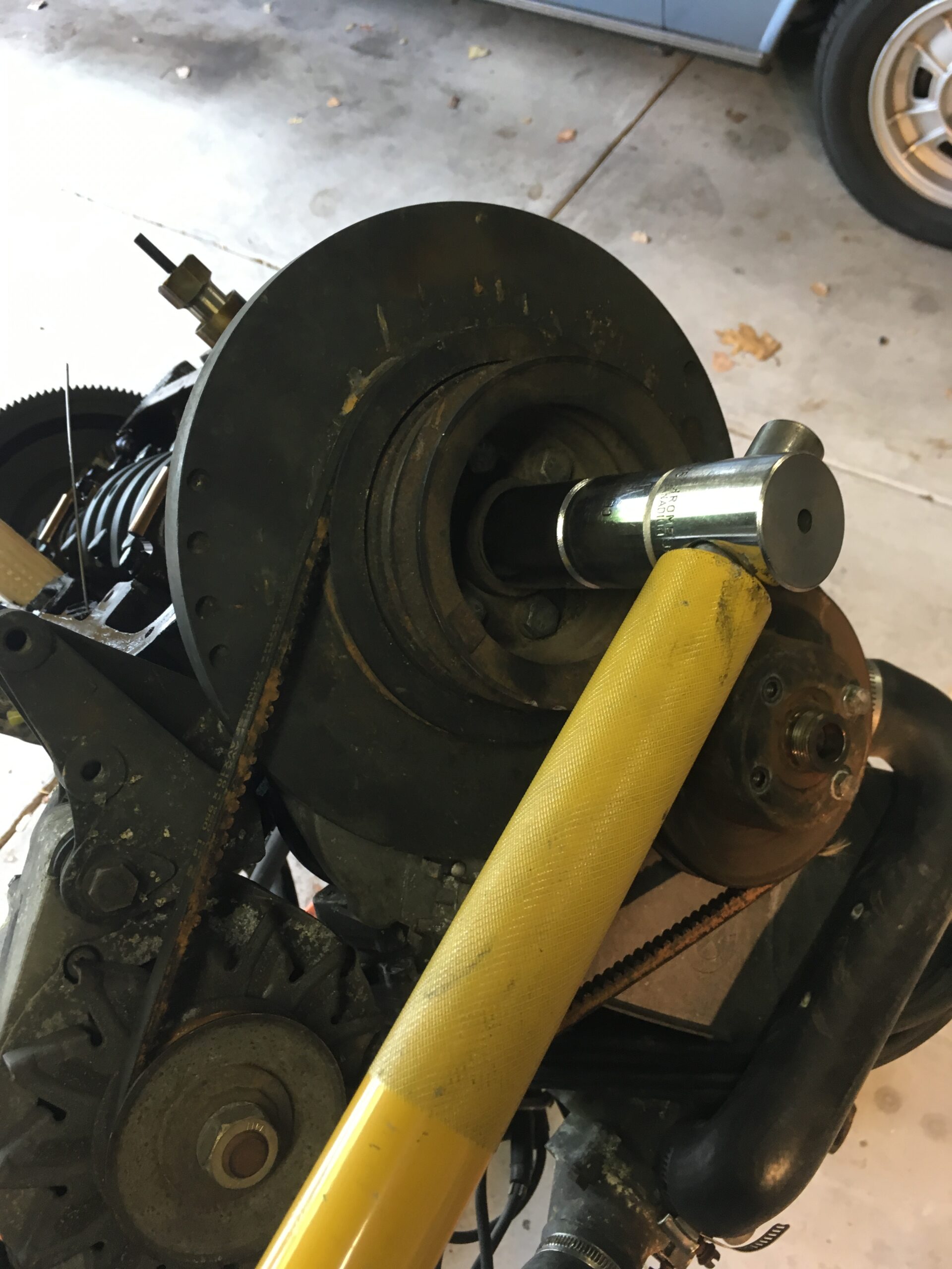
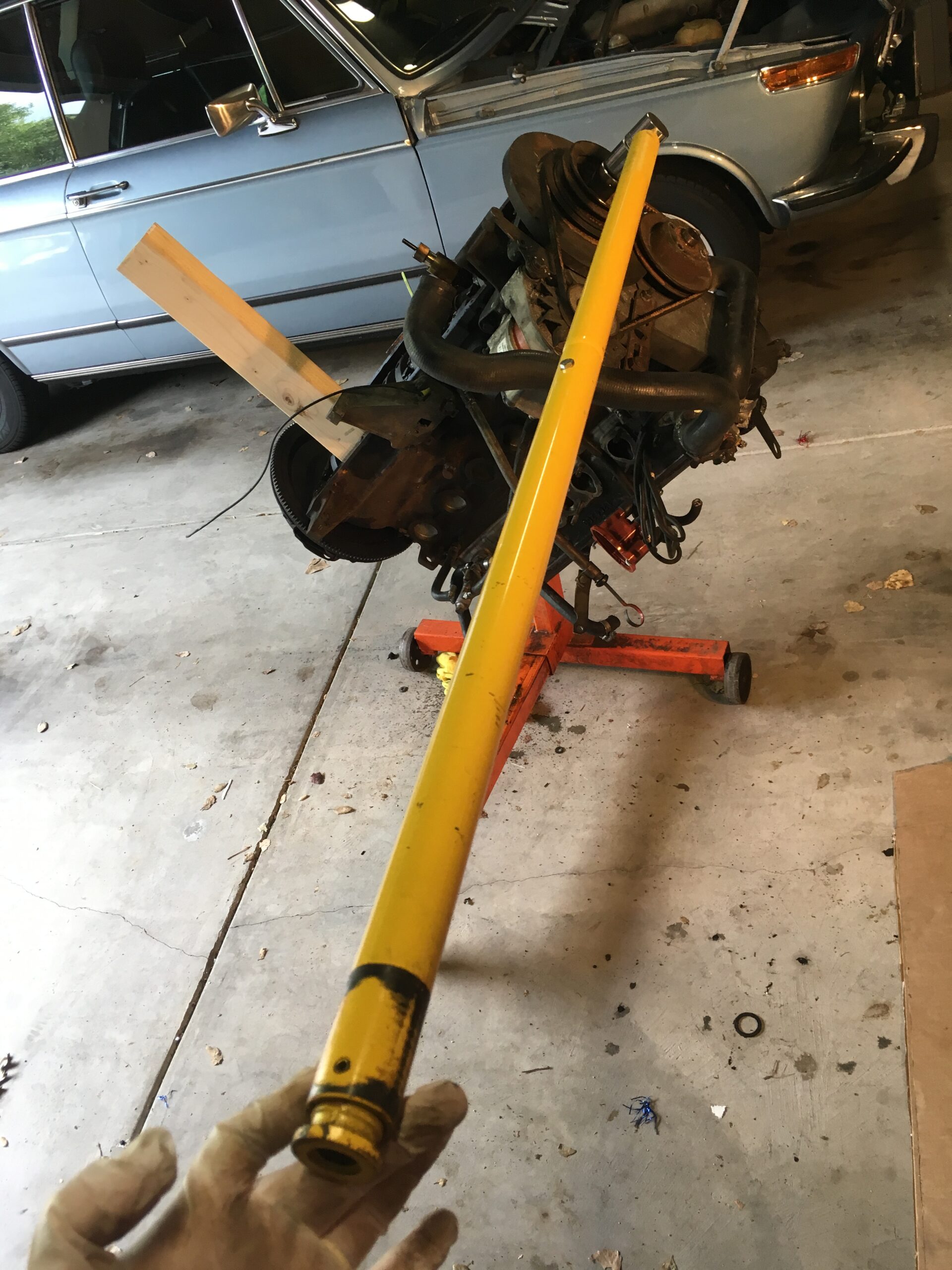
 To get to the main pulley the main crank nut had to be removed. Simple concept but considering it’s torqued to more than 300 ft/lbs…. I puzzled on that for a while, since my electric impact wrench wasn’t strong enough. Talked to a few friends, thus further delaying progress.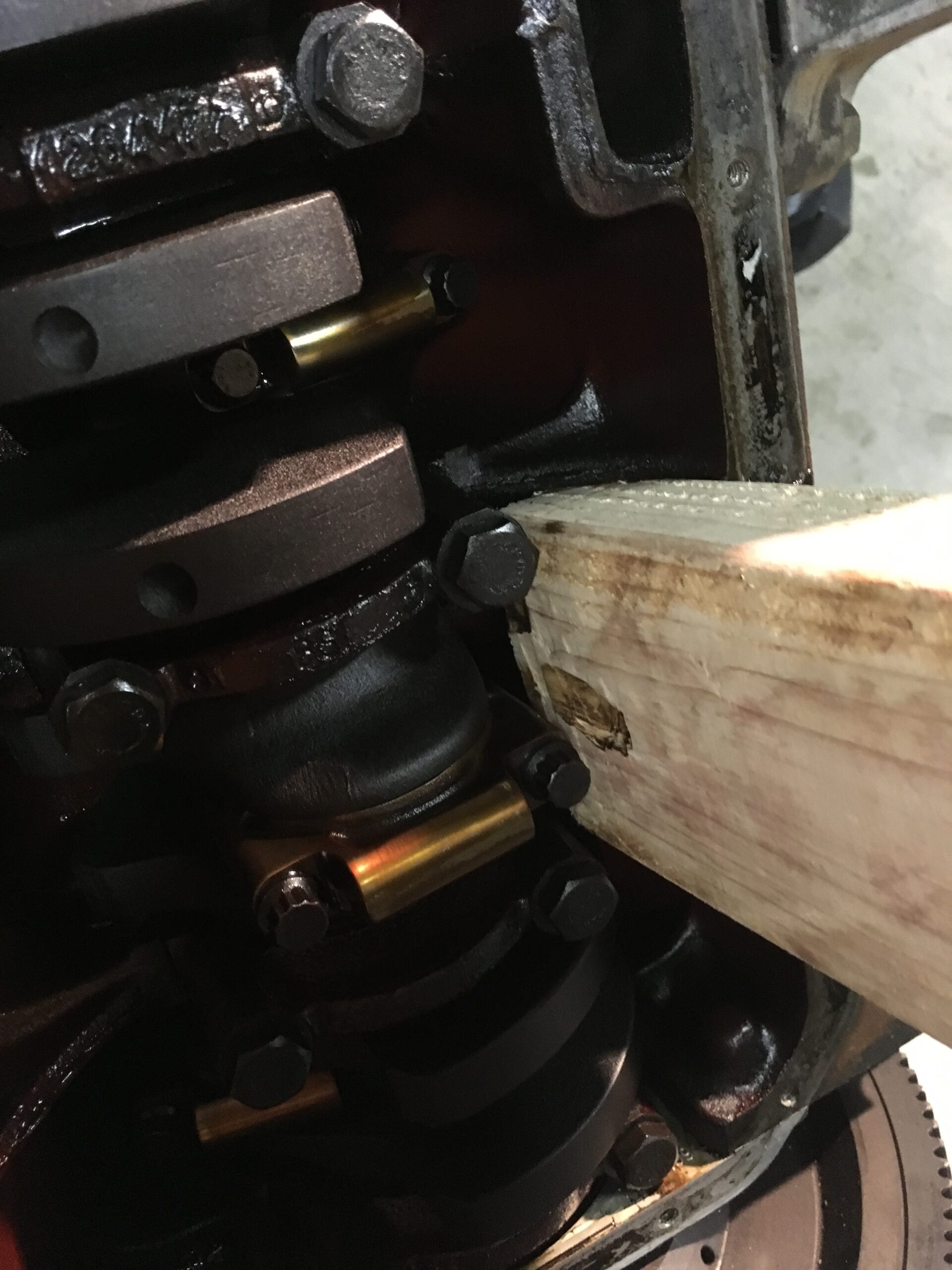
 Then main pulley had to be removed and that required a puller.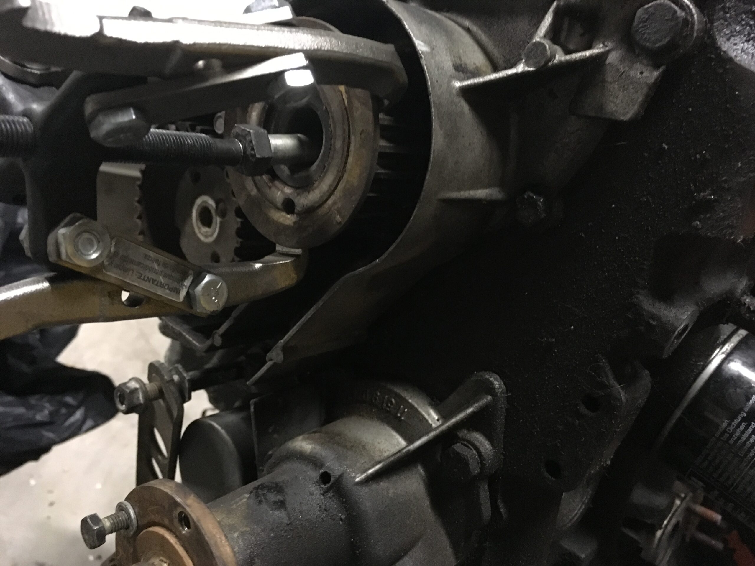
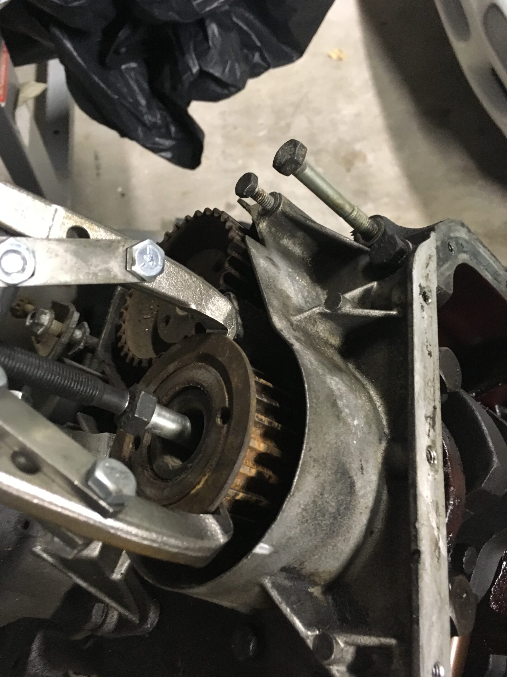
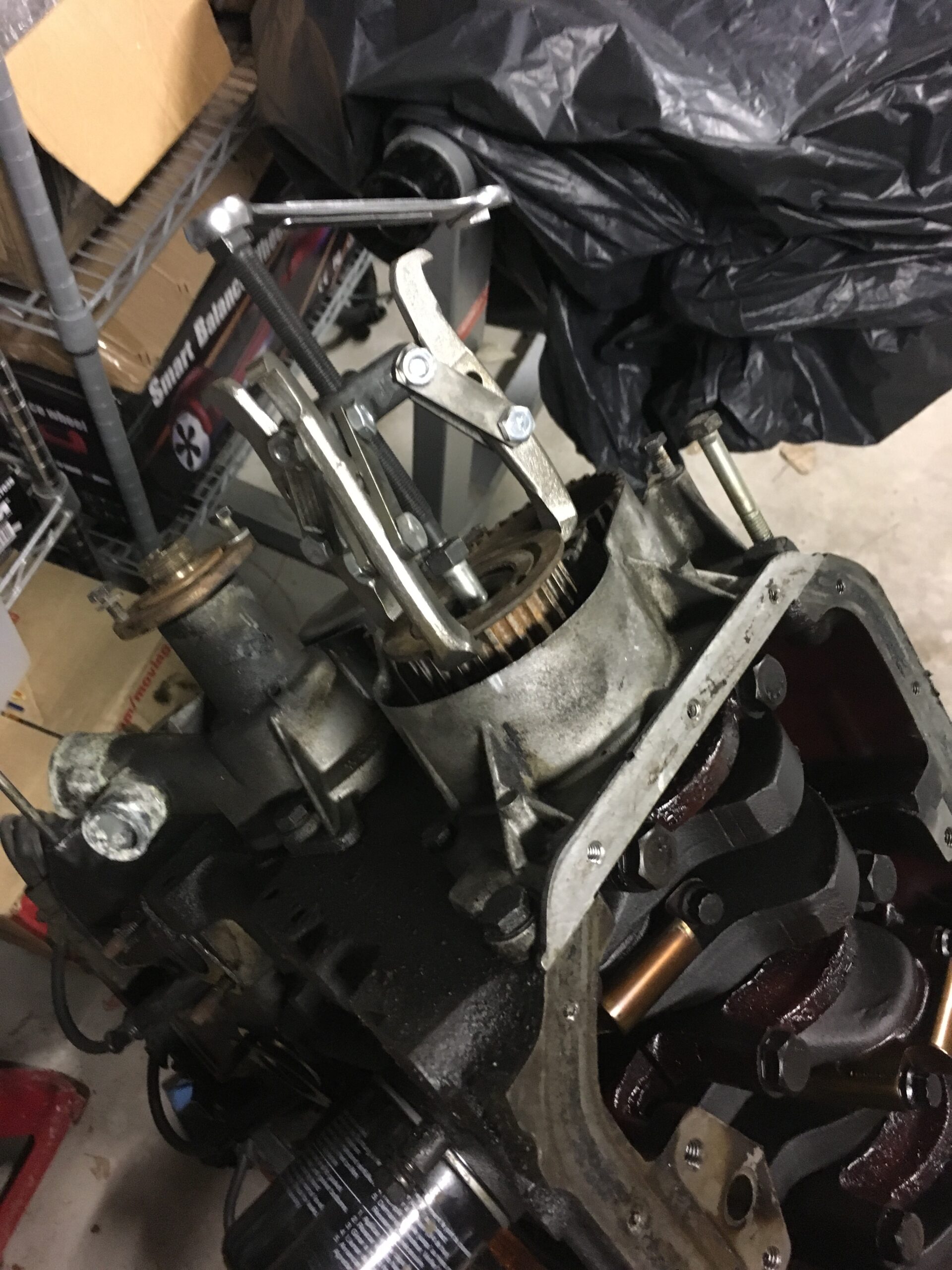 The rest of the front cover removal from the old motor and re-installation on the new one went smoothly.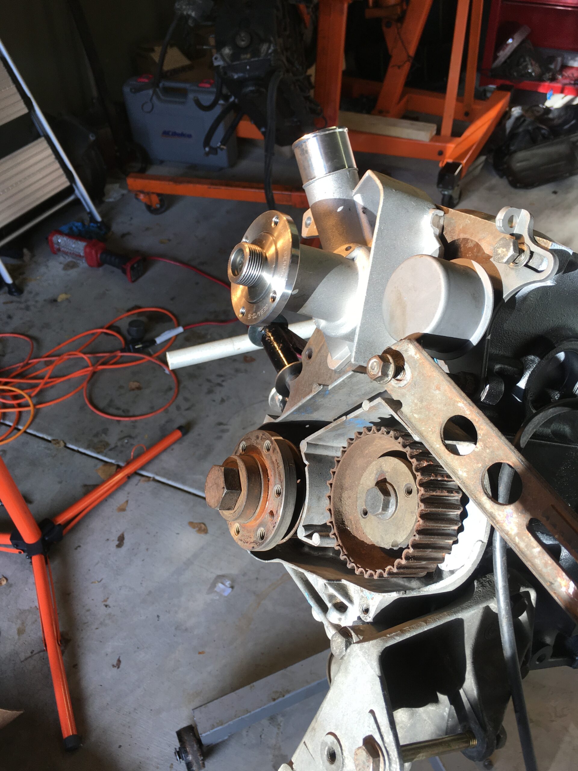
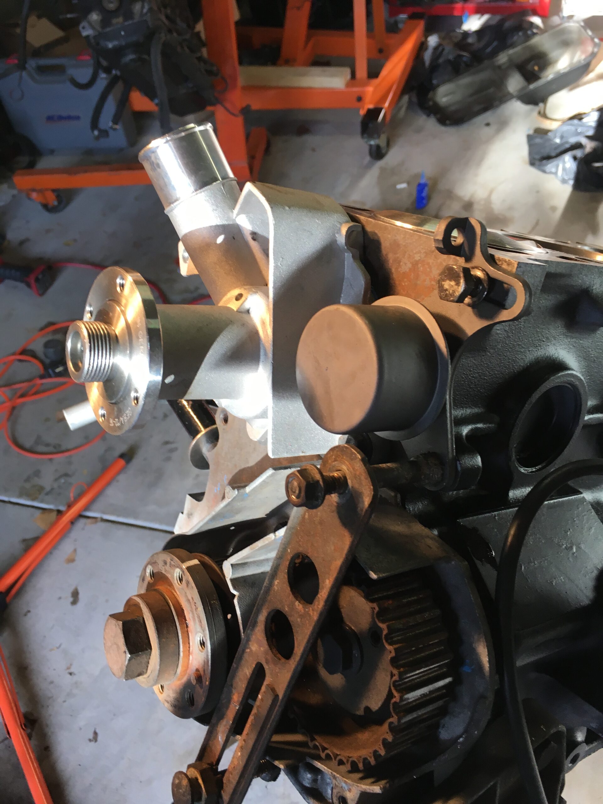 Next came the oil pump. Wait. Where is the new oil pump? Did I order one? How could I forget that? Couldn’t find one so I searched the invoices for the various parts I ordered. None included an oil pump, so that needed to be ordered. Another delay. While waiting I took the pressure relief valve off the old engine and put it on the new.
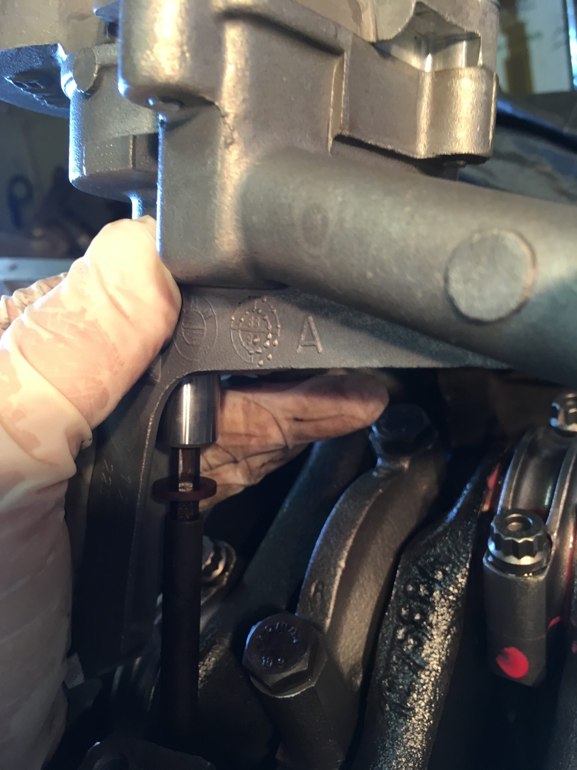
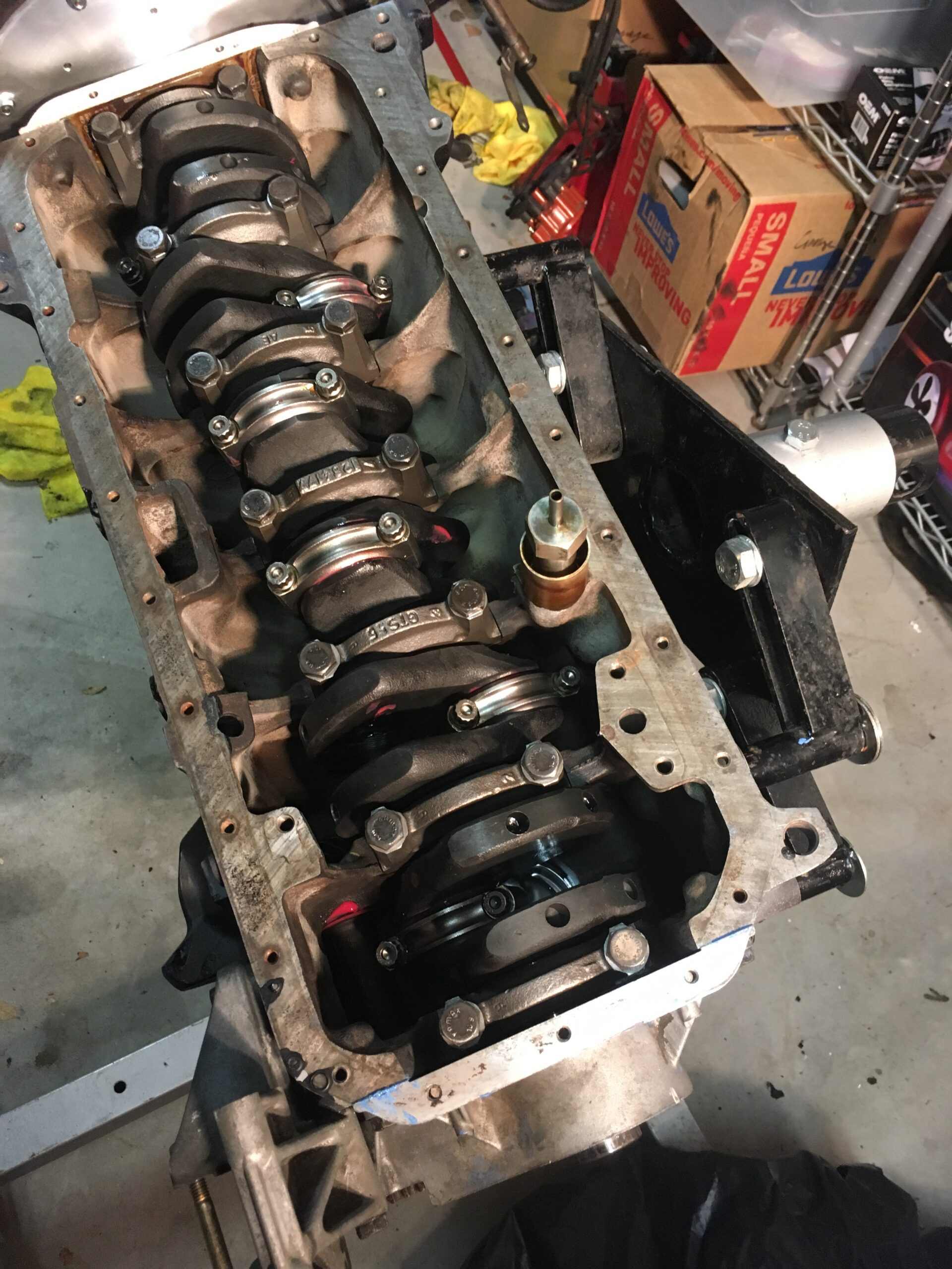 Once the oil pump was in hand, I mounted it on the underside of the block. First a test fit, with the drive and then locktite on the bolts. But, since I never worked on an M20 before I didn’t know how the pump (and distributor) was driven. Hence my introduction to the intermediate shaft and the drive off the belt. Some momentum was building, after all the delays, but it was still over a month since the last update here.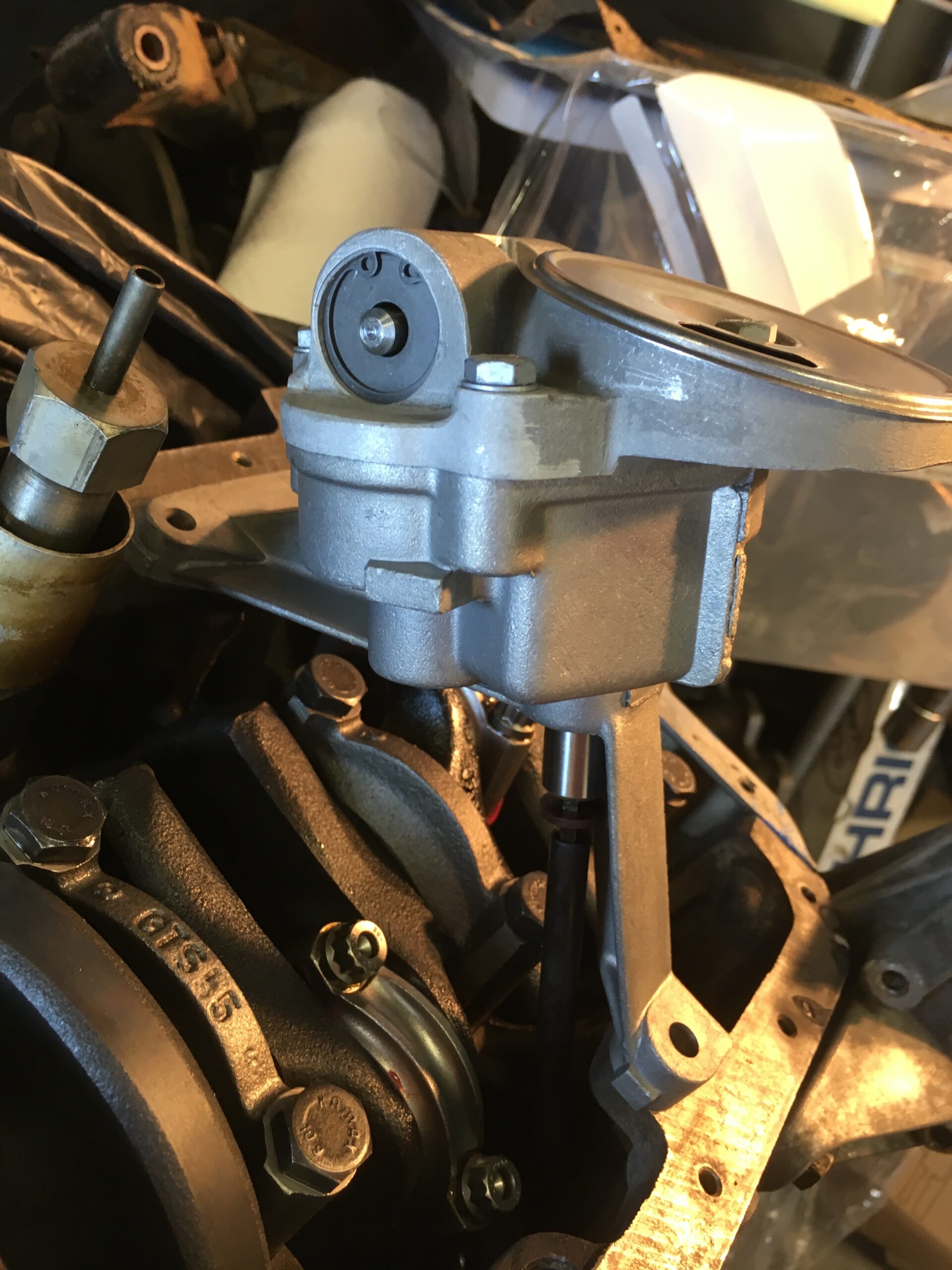
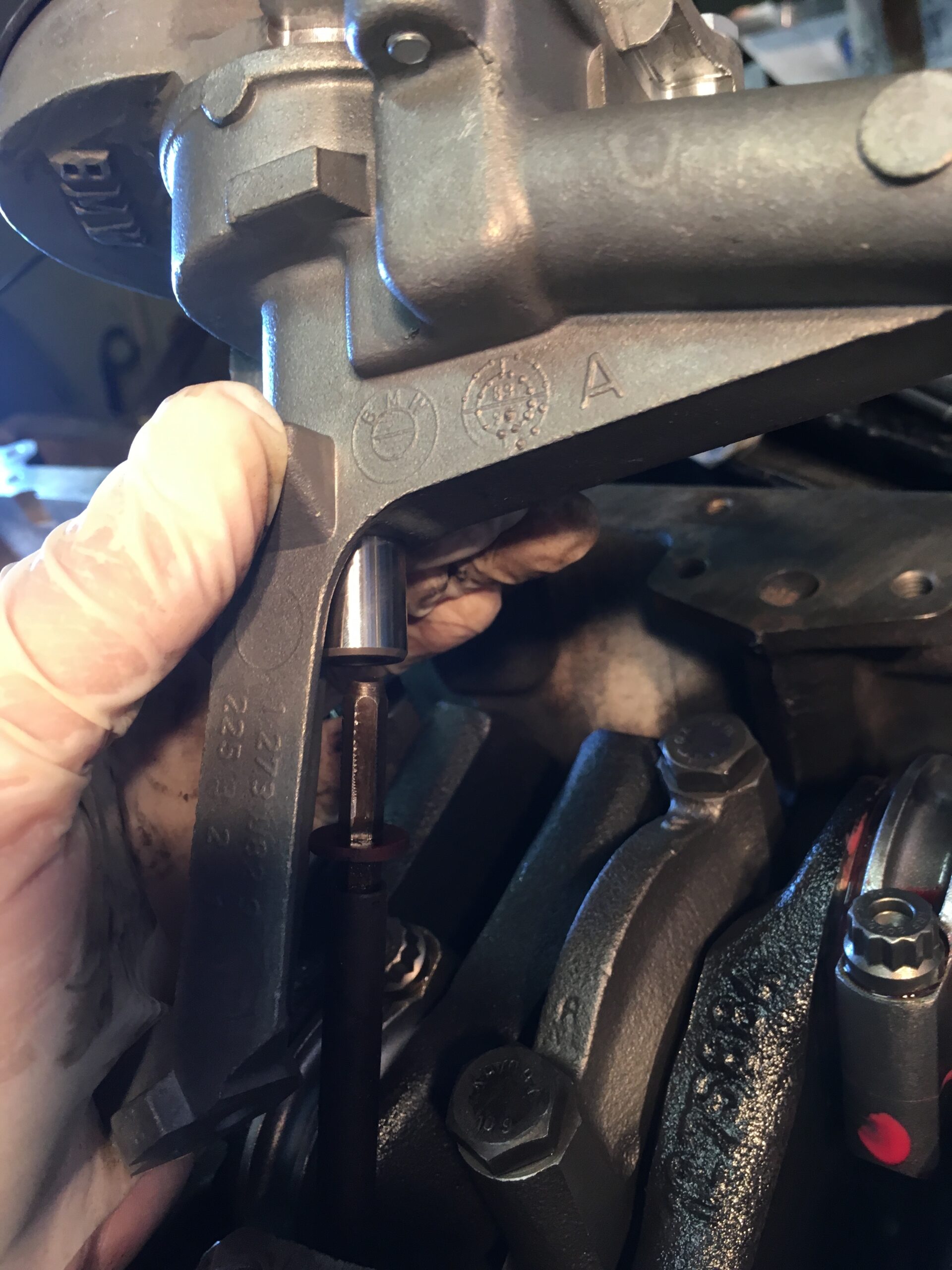
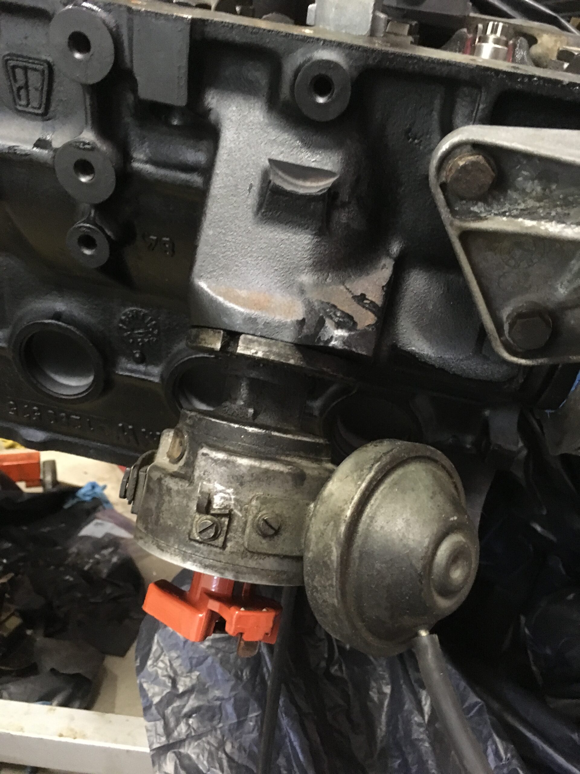
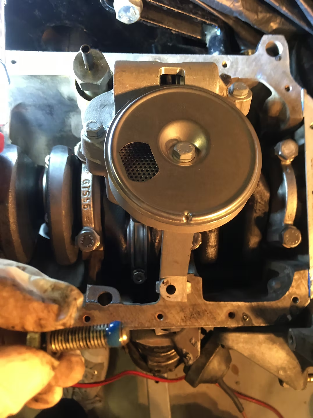 The distributor went in.
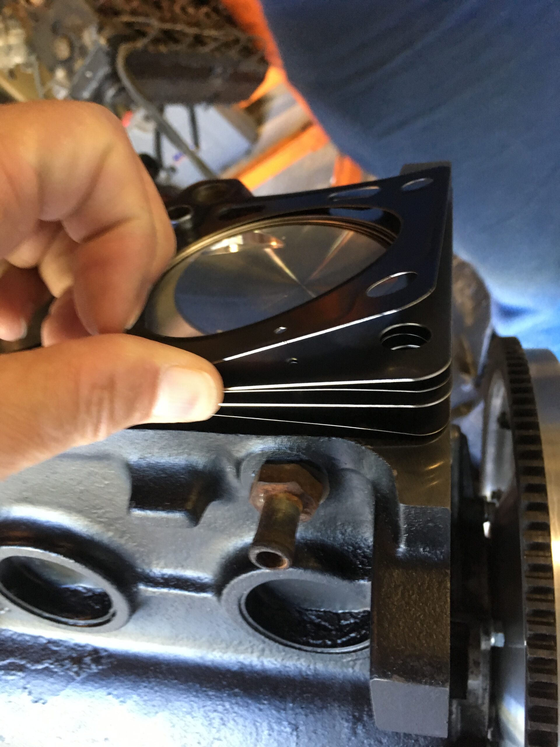
 The head gasket on the block. The head gasket itself is unusual, a metal one that had to be custom made because of the boring out of the block.
 The head on that (thanks Frank for the help).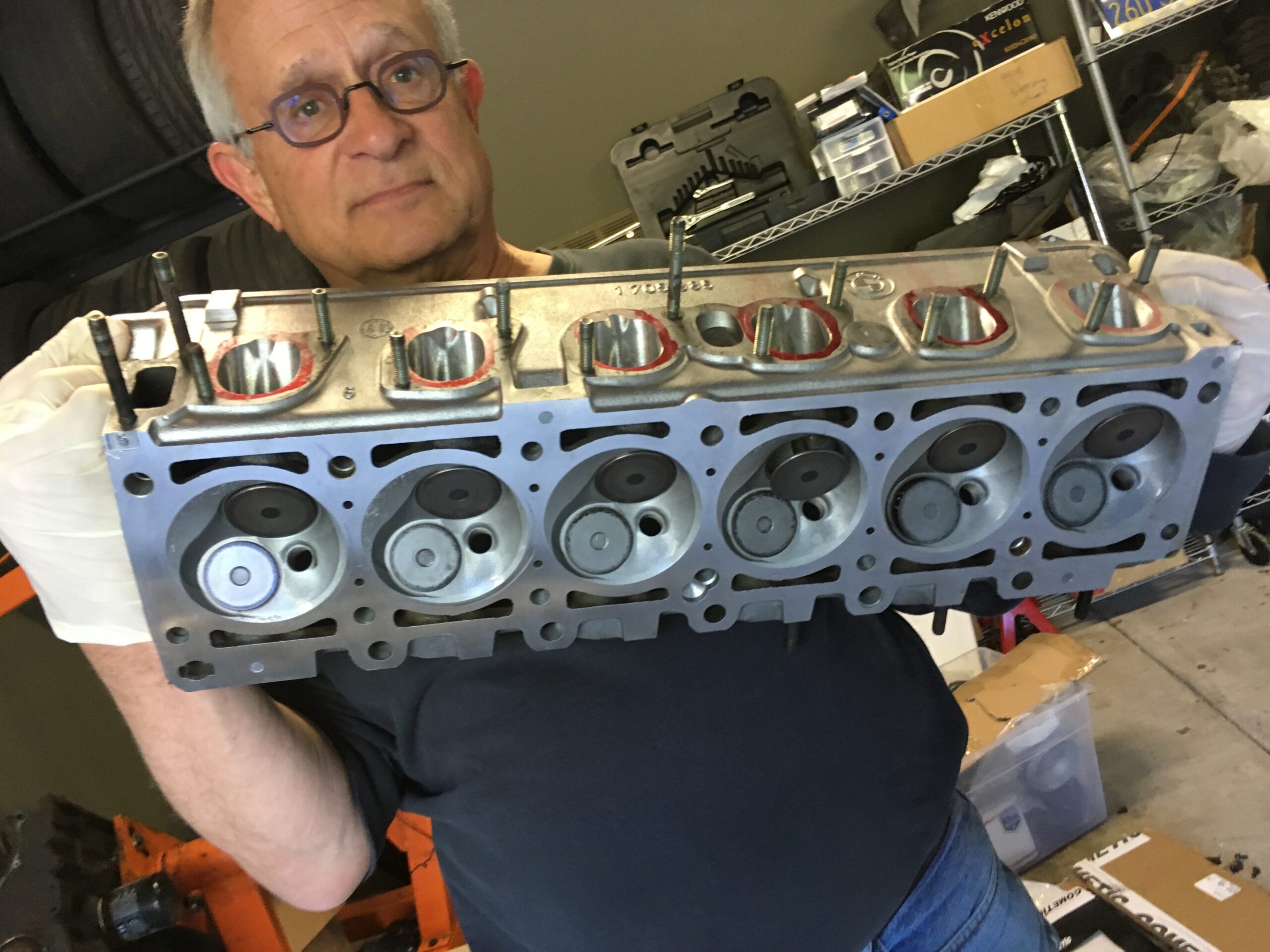
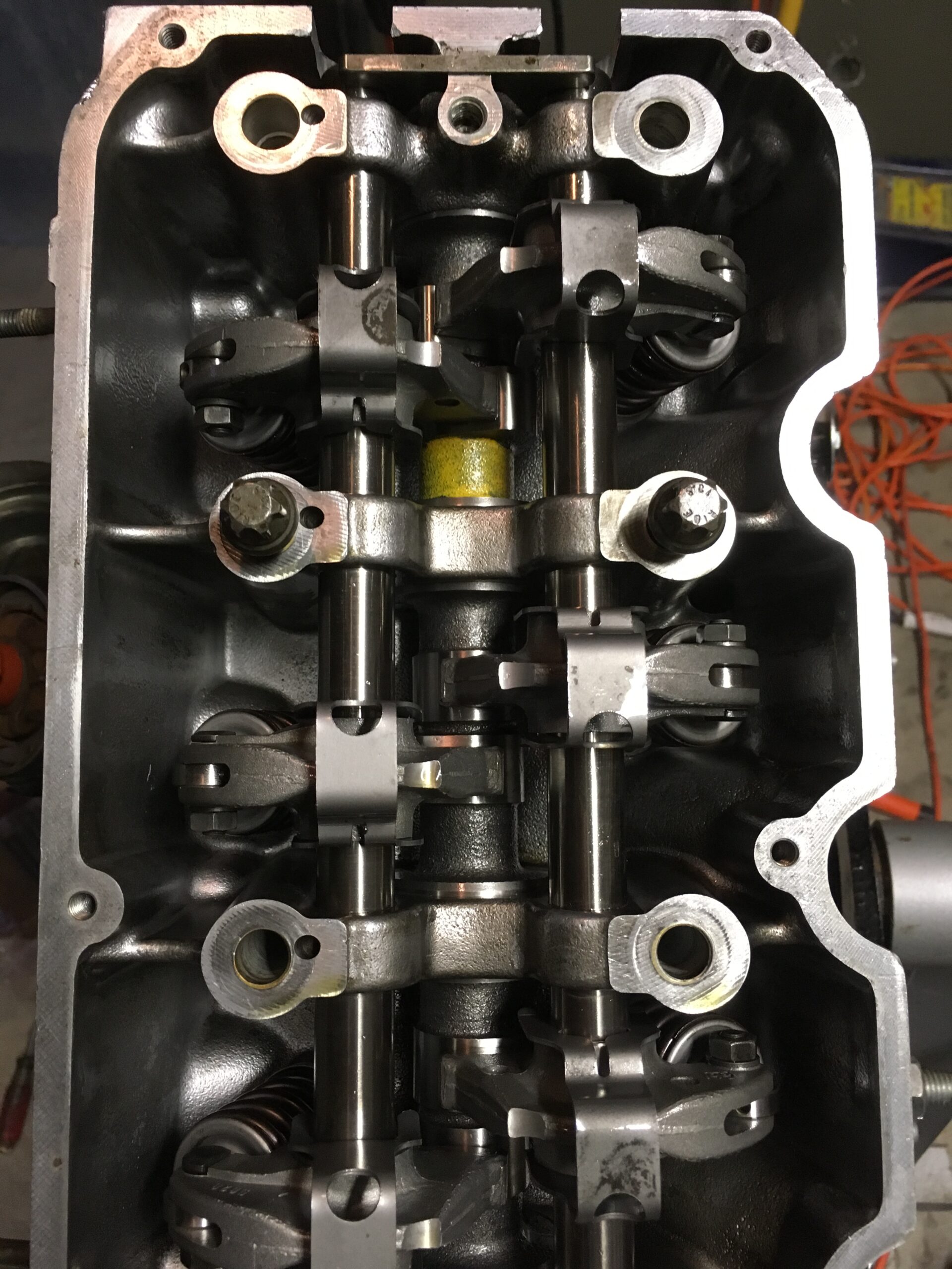
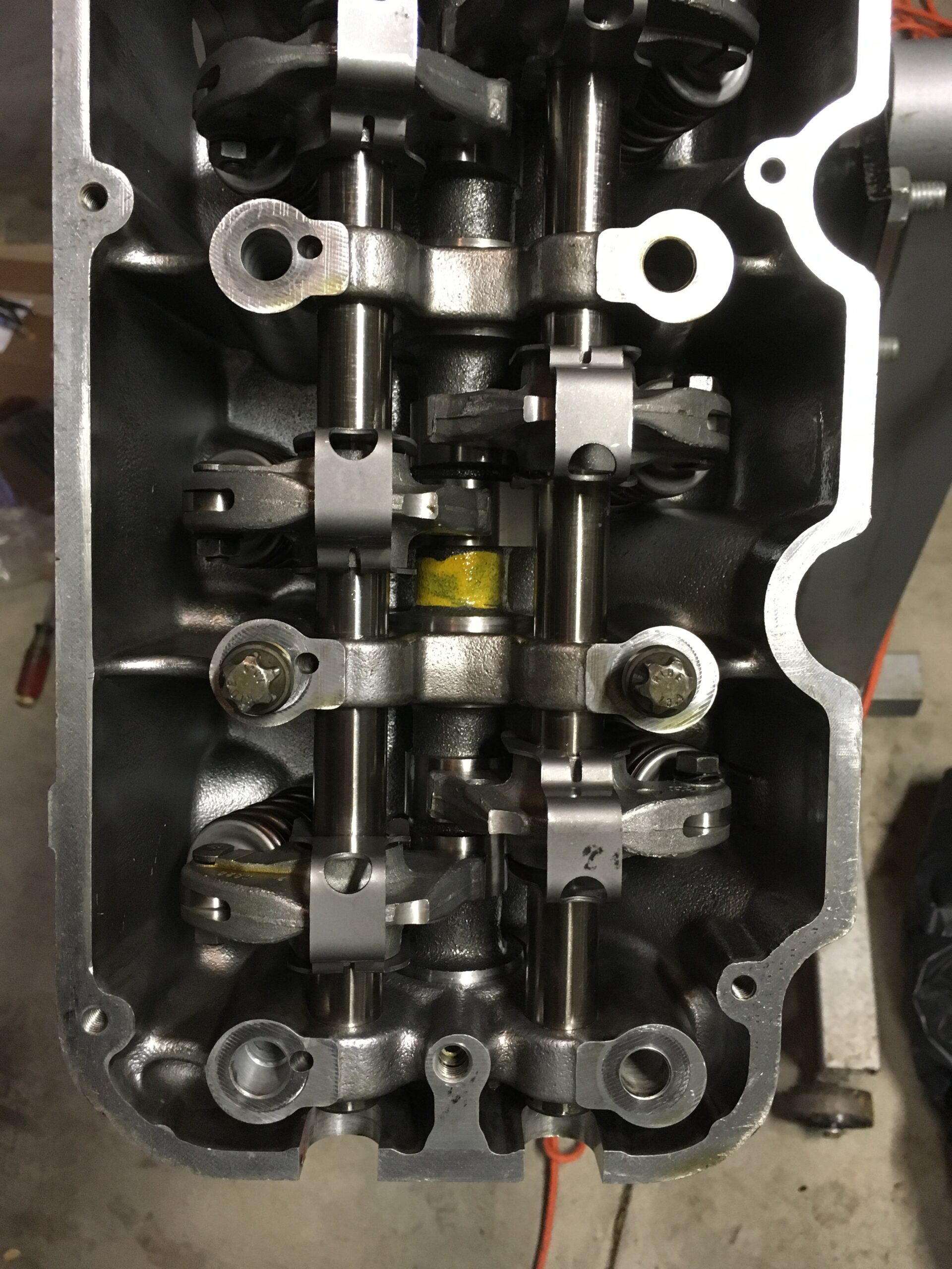
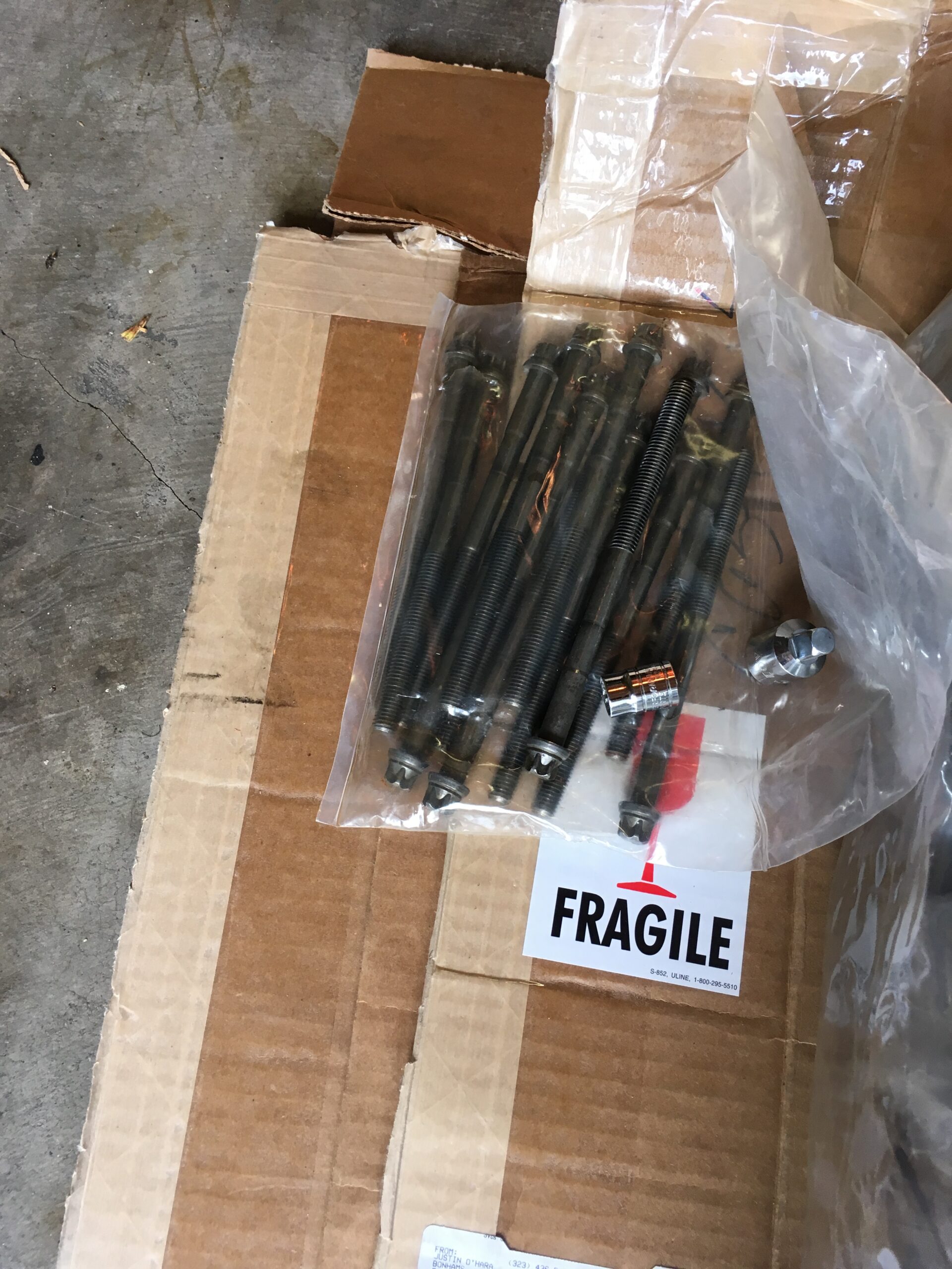
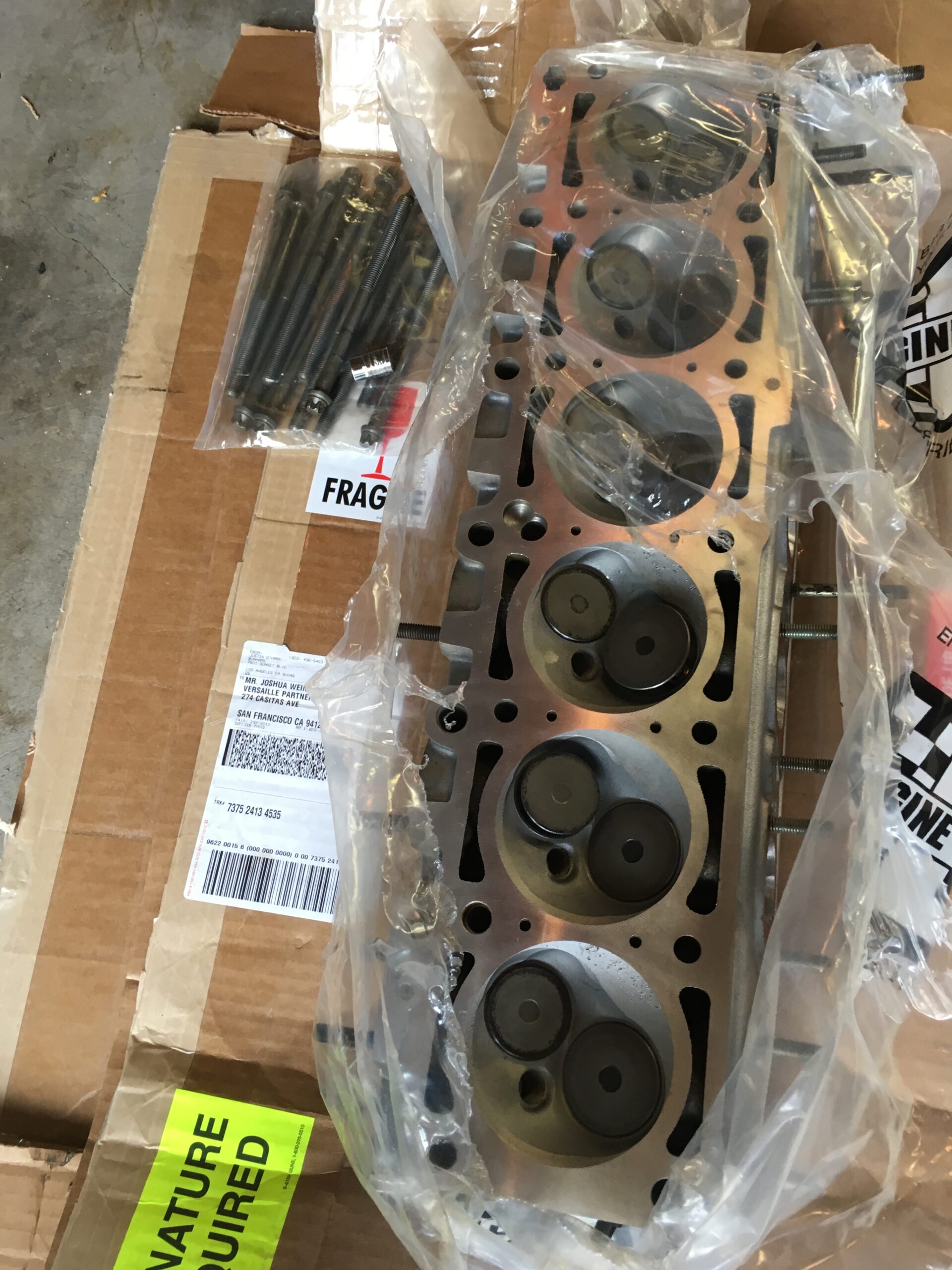 But, wait, where are the washers for the head bolts? Nowhere – not ordered. Another delay. Calls to the local BMW dealers showed none in Northern California, so another parts order and another delay.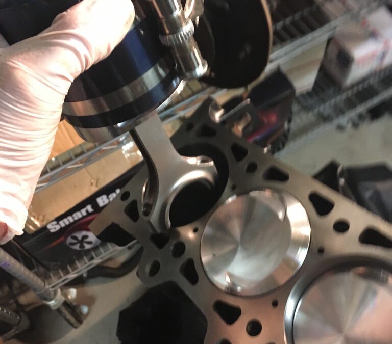
 Then, on goes the ring compressor.
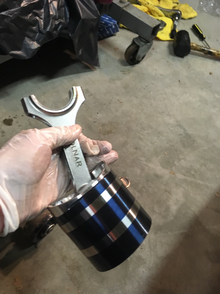 And placed in the block (with rod bearing installed and assembly lube applied. Also, make sure the crank journal for that cylinder is at the bottom of its stroke, so the con rod doesn’t ding it (don’t ask me how I learned that lesson!).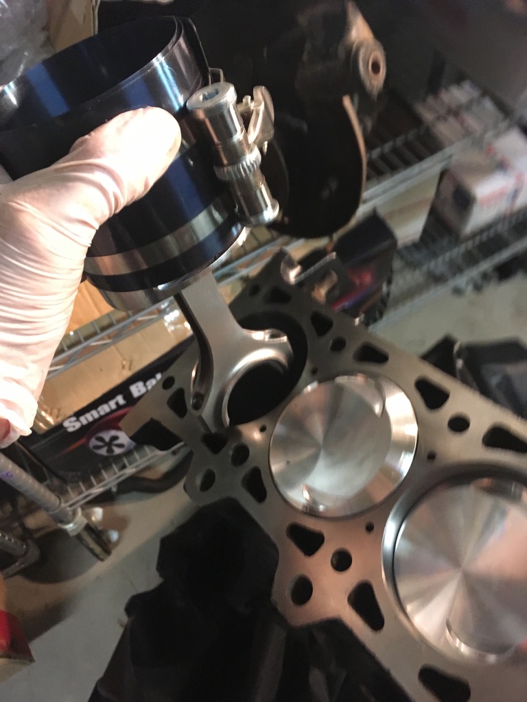
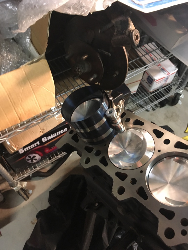 And placed in the block (with rod bearing installed and assembly lube applied. Also, make sure the crank journal for that cylinder is at the bottom of its stroke, so the con rod doesn’t ding it (don’t ask me how I learned that lesson!).
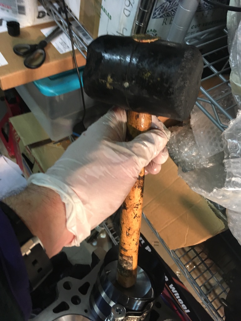 One at a time.
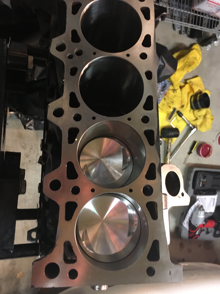 Eventually, all six are in.
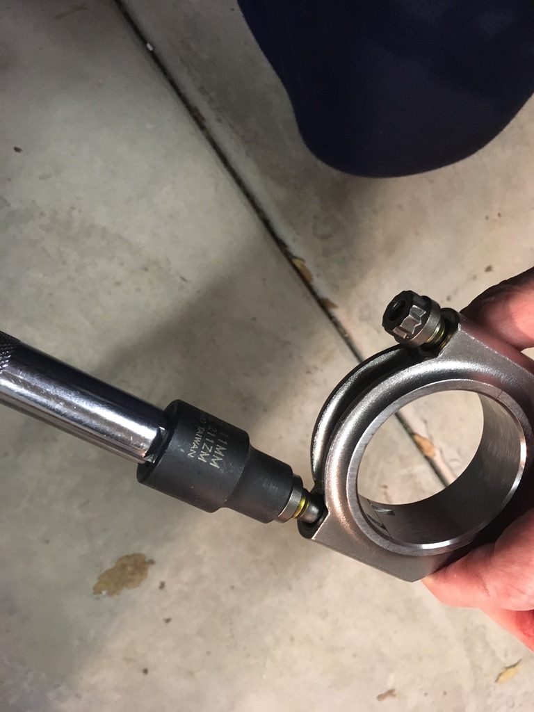
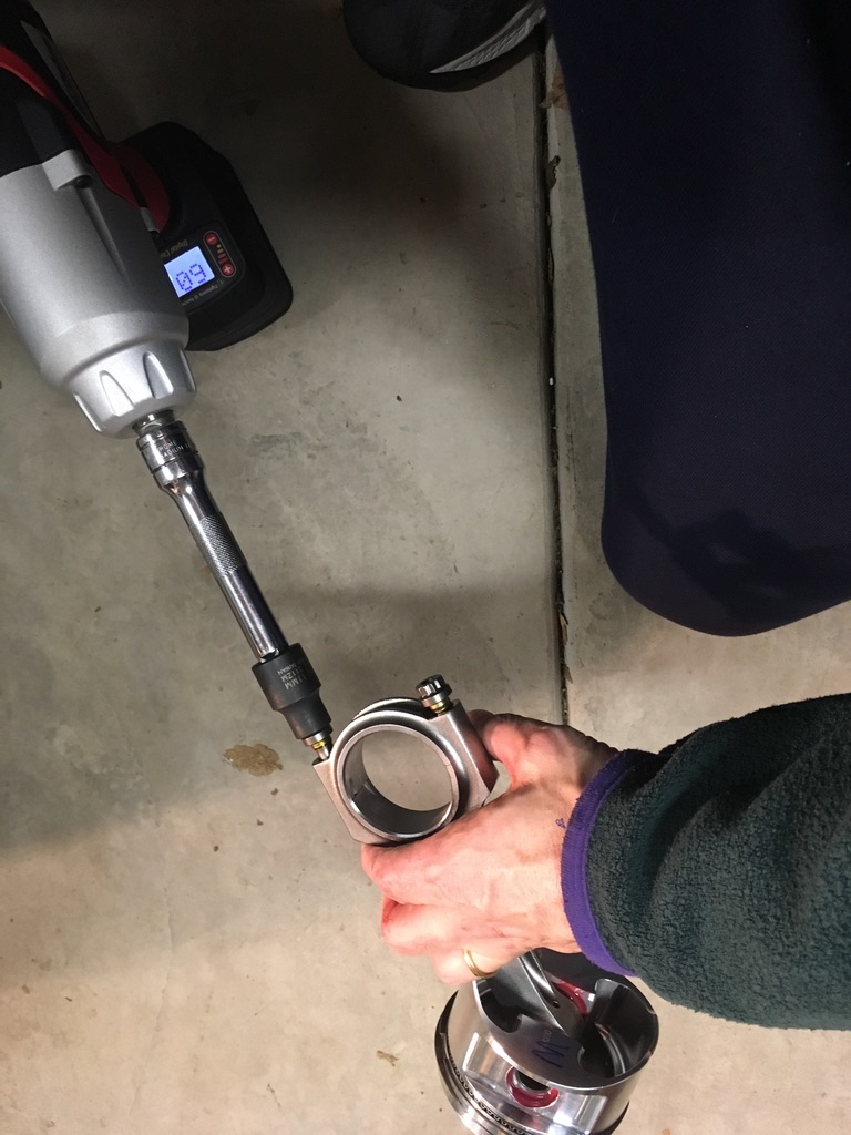
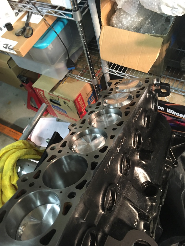 Torque the rod bolts.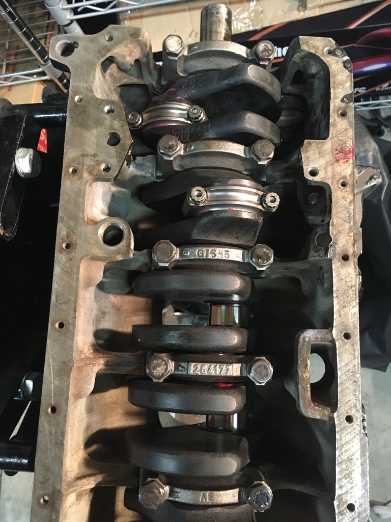
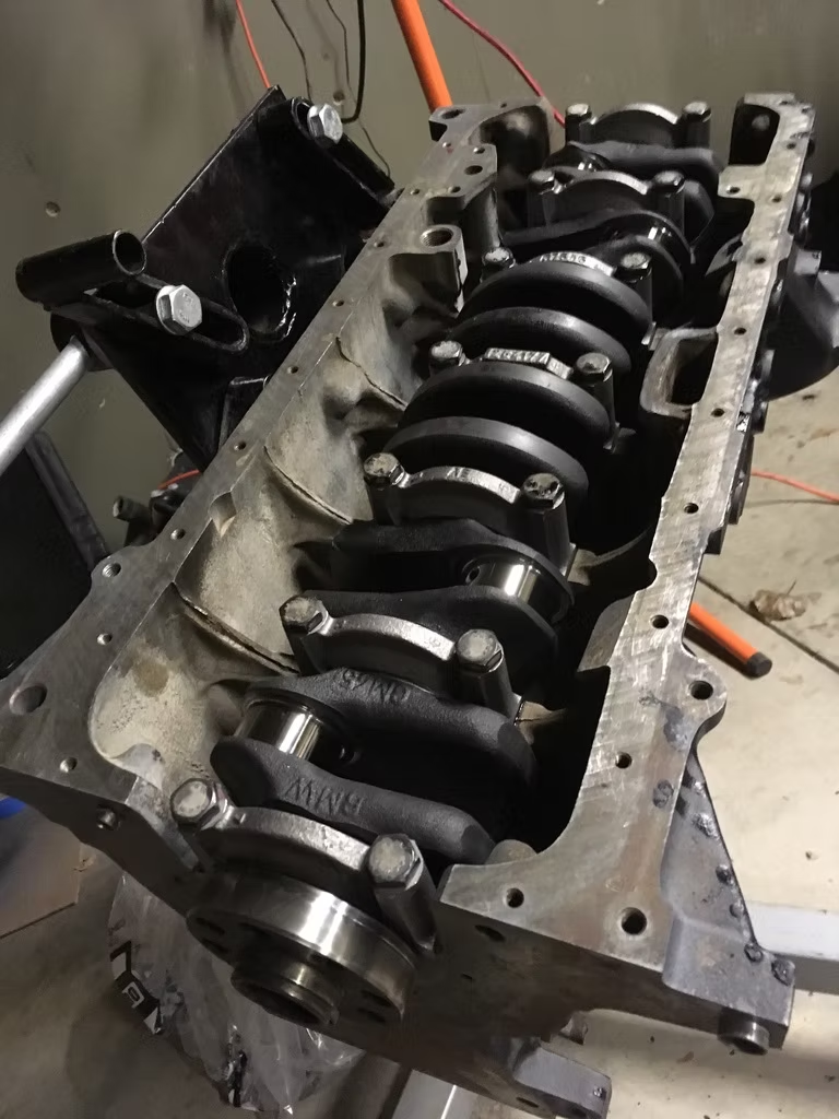 And if you’re lucky, it still turns.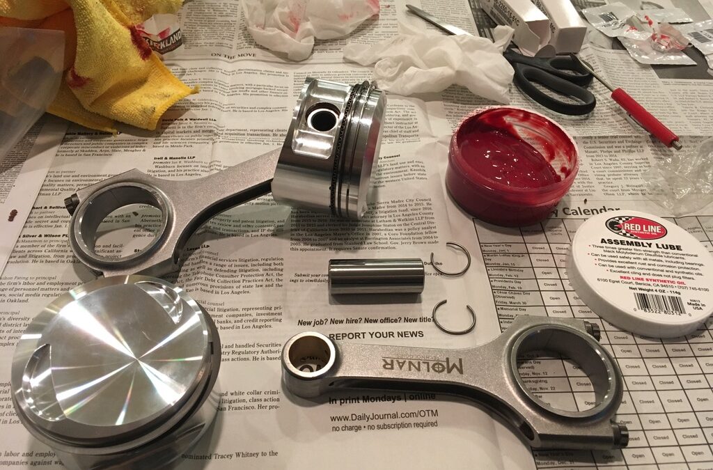
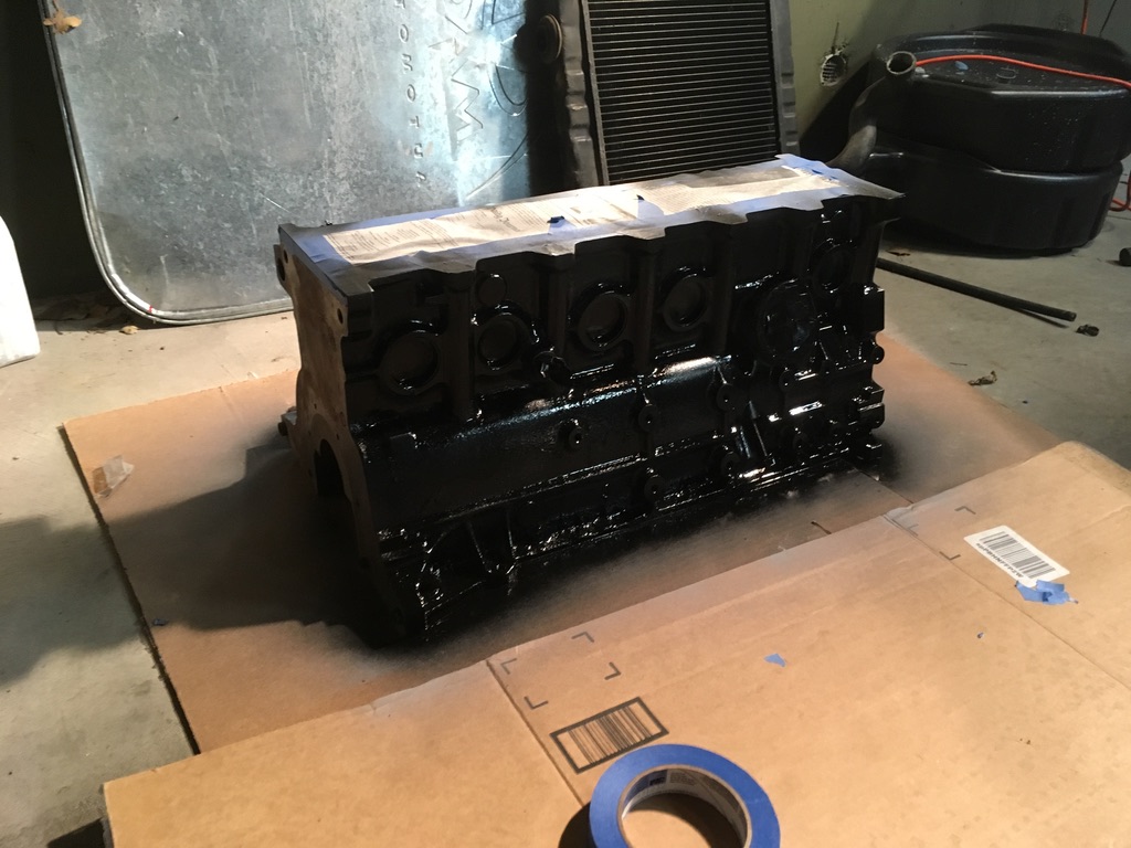 Then I tried to figure out which way the end caps went (internet research helped as it wasn’t obvious from trying to fit them).
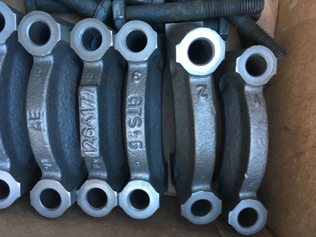 With the order and orientation of the end caps clarified, it was time to install the rod bearings in the block.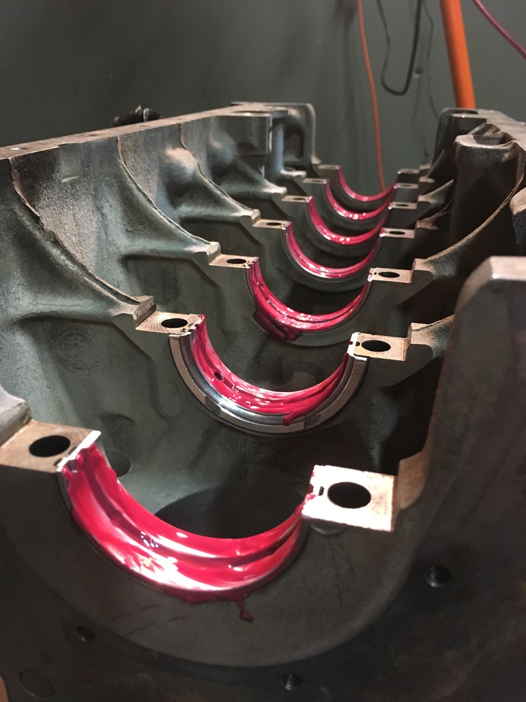
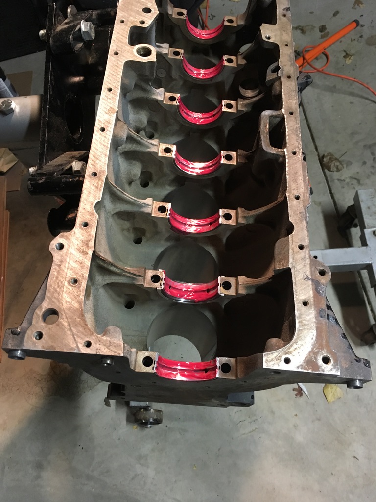 And the end caps.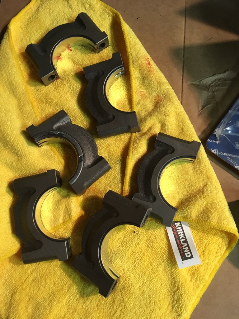
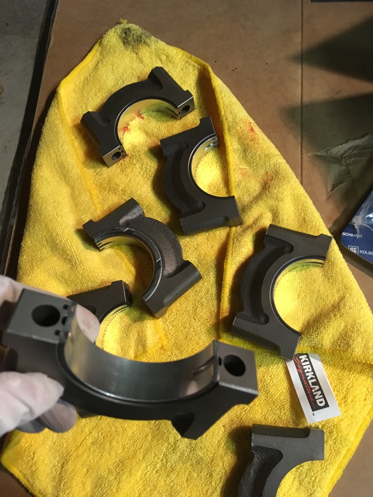 Then it was time for the turbo diesel crank.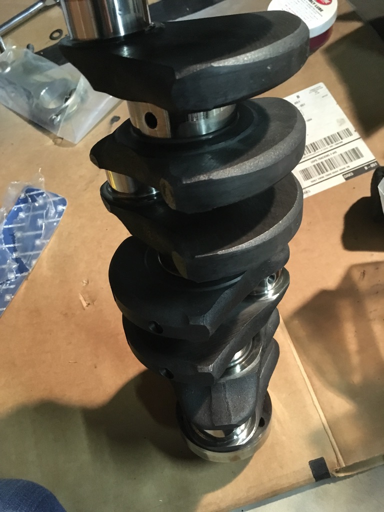
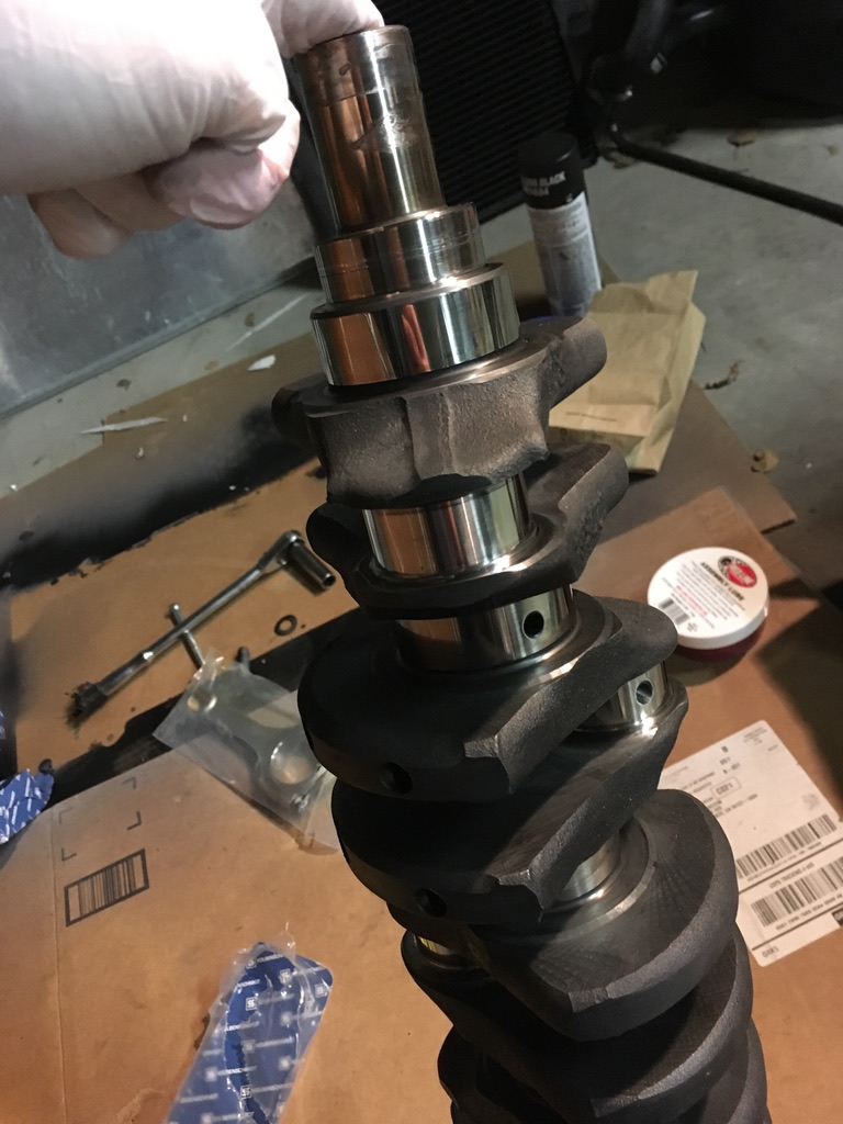 Gently place the crank in the block.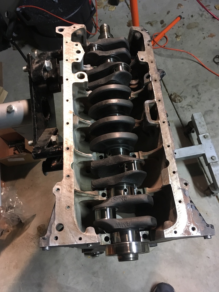
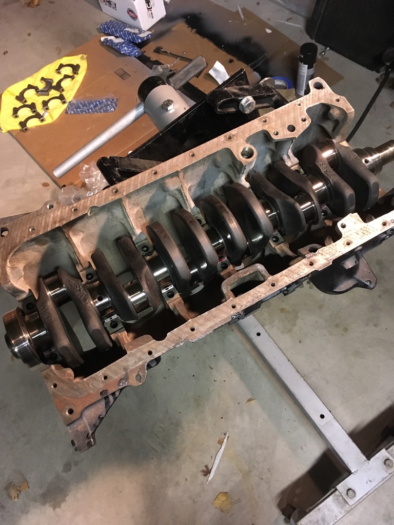
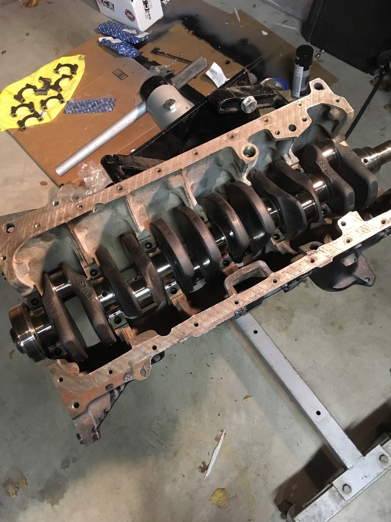 And install the end caps with bearings.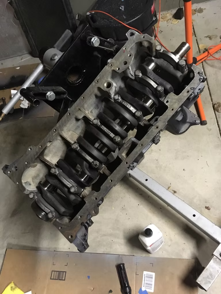
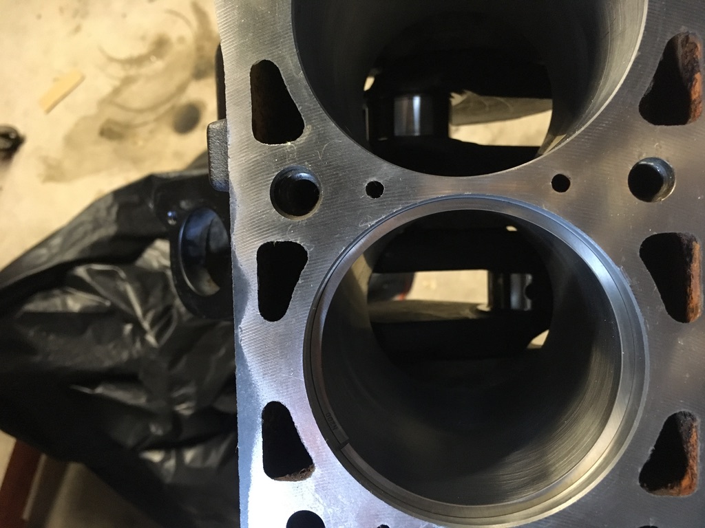
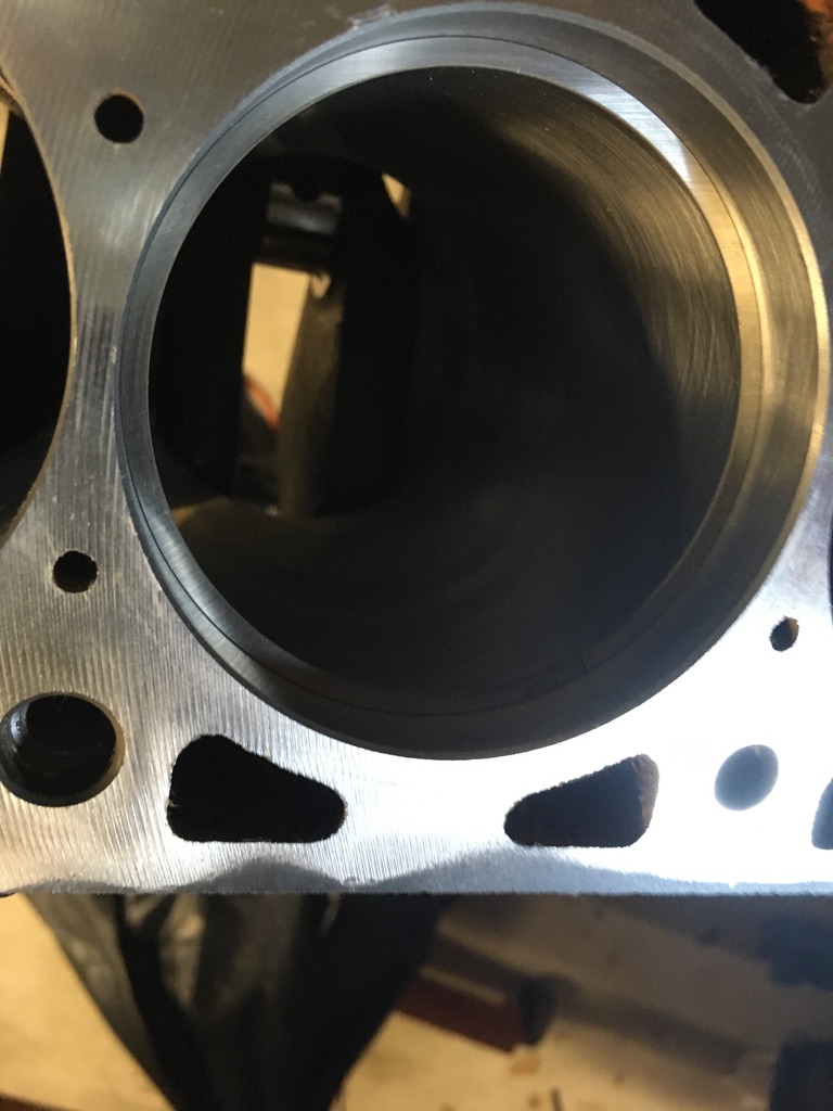
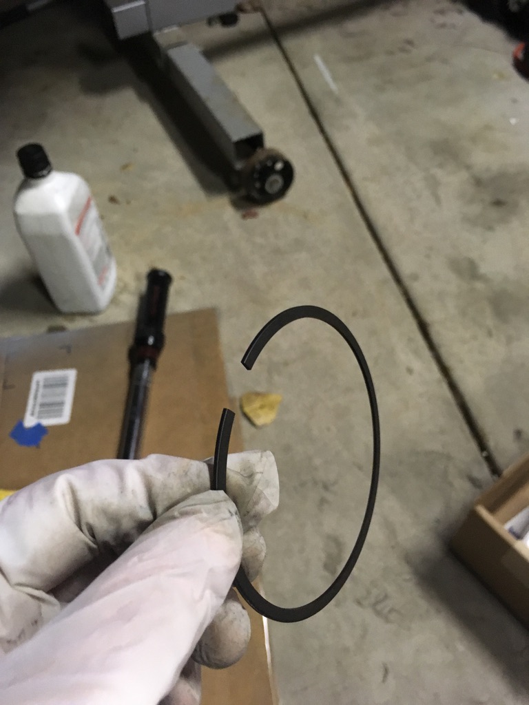
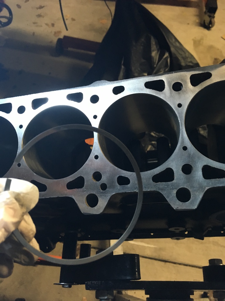 And install them on the pistons.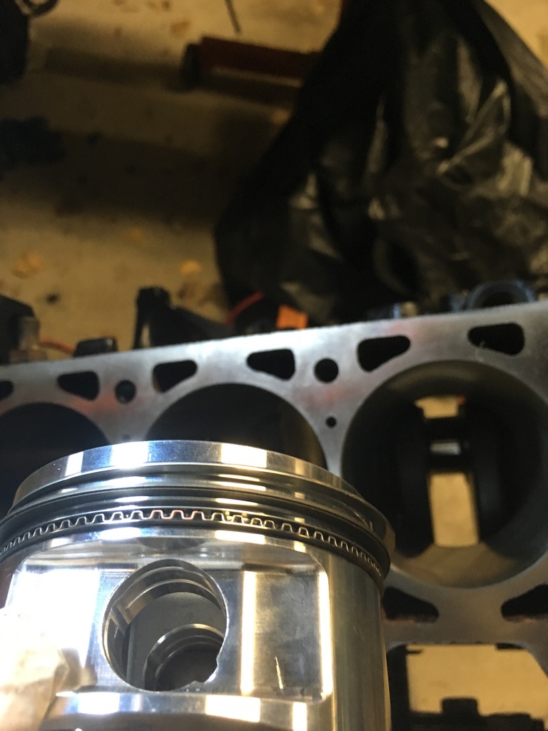
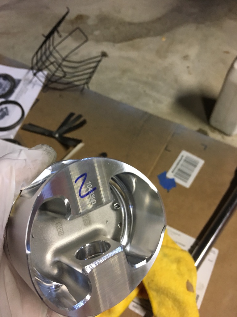
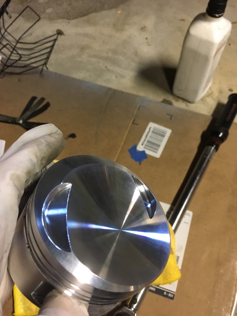
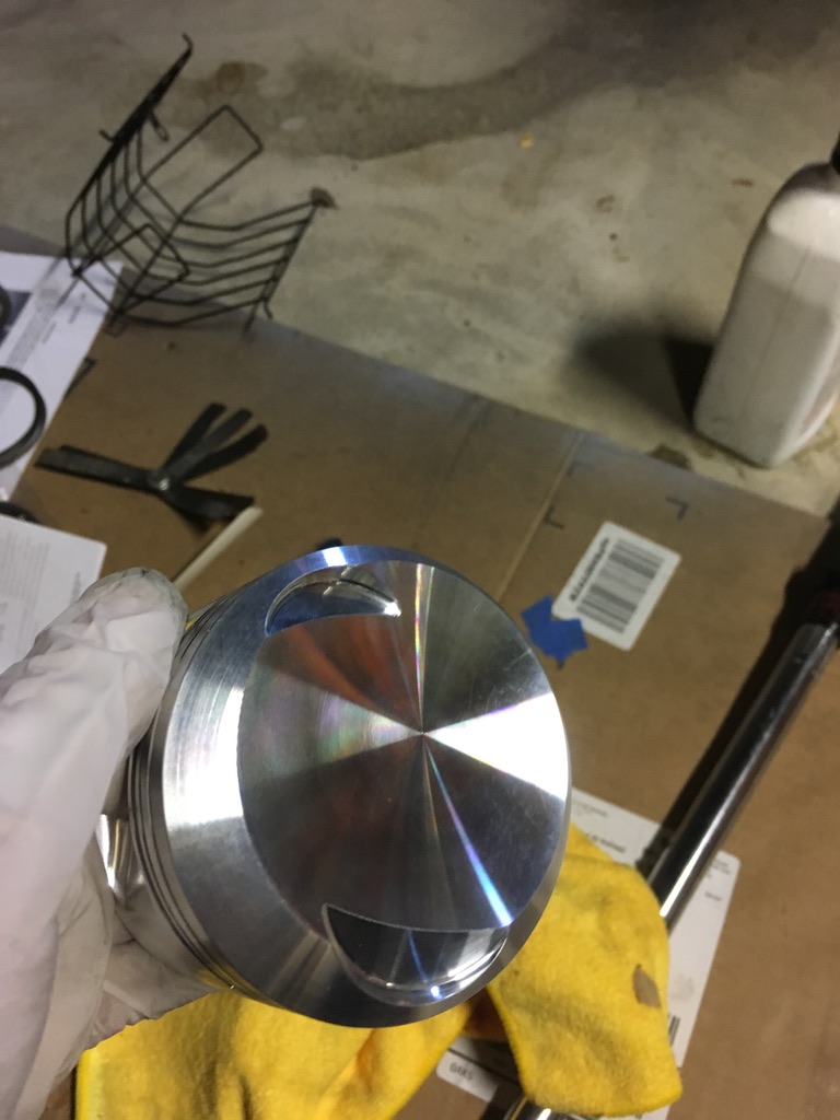
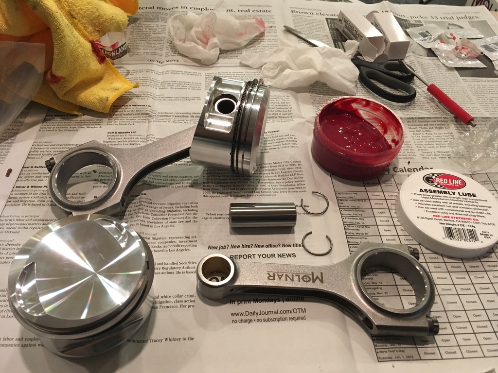
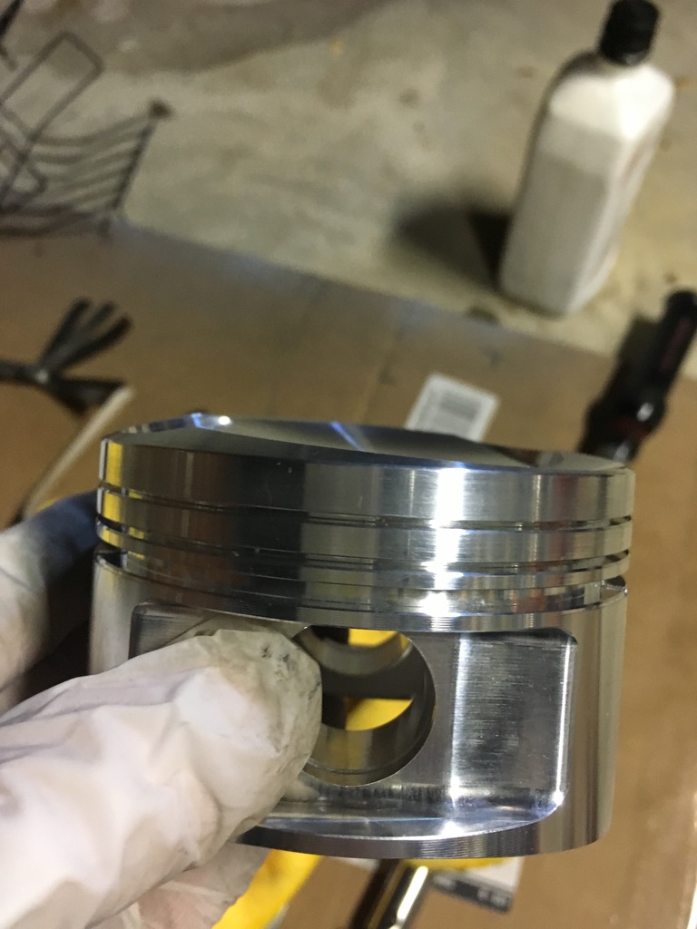 Then attach the rods to the pistons. The hardest part being, without the right tool, installing the wrist-pin retaining clips.